-
-
October 4, 2023 at 3:58 am
Julio Mariano Geronimo
SubscriberBelow is my LNA cascode inductive source degeneration circuitry:
I am having a hard time figuring out how to ensure that my transistors are biased properly. I do not know where or how to start. I understand that the current mirror circuitry relates to the transistor biasing but one of the requirements for the current mirror to work is to ensure that M1 and M3 are operating at saturation region. But how do I check that M1 and M3 are operating in their saturation region?Â
Would really appreciate the help for I have been trying to figure this out for several days.Â
-
October 25, 2023 at 2:11 pm
Praneeth
Ansys EmployeeHi Julio Mariano,
Thank you for reaching out to the Ansys Learning Forum. Your patience on this query is much appreciated.
Please setup some demo or example circuits using these transistors for testing if you are getting the desired response. This way, you can be sure that the transistors are working in saturation. Then you can implement this circuit of yours. If you need more information on the transistors models that you are using, then kindly go through the "Circuit Components" under the Circuit Help menu.
There is a getting started guide in parts on designing LNAs under the Circuit pdfs available in the same Help menu.
Best regards,
Praneeth.
-
- The topic ‘
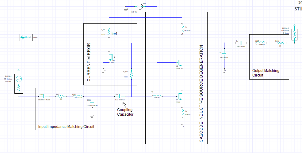
Cascode Inductive Source Degeneration LNA Transistor Biasing’ is closed to new replies.
-
6369
-
1906
-
1457
-
1308
-
1022
© 2026 Copyright ANSYS, Inc. All rights reserved.
