Ansys Assistant will be unavailable on the Learning Forum starting January 30. An upgraded version is coming soon. We apologize for any inconvenience and appreciate your patience. Stay tuned for updates.
Electronics

Electronics

Topics related to HFSS, Maxwell, SIwave, Icepak, Electronics Enterprise and more.

Calculation with Skew in Motor-CAD

    • matthew.crossley
      Subscriber

      Dear All,

      I have been working with a step skewed permanent magnet machine in Motor-CAD and was attempting to understand how the calcualtion is performed. The Motor-CAD manual provides the following statement: "Skew (mechanical degrees) ... Rotor - with this option the rotor is split into several slices, the length of each slice and its angle of rotation is specifed in the table. Calculations are run for each slice and the results combined to give the machine performance" 

      Does anyone have any further information about the method of calcualting performance with a step skewed permanent magnet rotor, i.e. how the performance is calculated for the different slices and the method of combining the results?


      Many Thanks

      Matthew


    • James Packer
      Ansys Employee

      Hi Matthew,

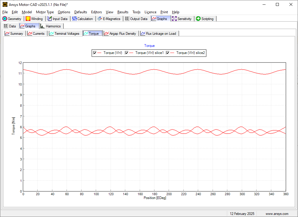
      Motor-CAD is effectively running a series of independent 2d electromagnetic calculations for each slice, with the rotor starting angle depending on that slice's skew angle. The results are combined by simple addition. For example, the transient torque for the whole machine is simply the sum of the torque from each slice. Similarly the terminal voltage or back emf for the whole machine is a simple addition of the single slice results. Of course if the slices are of different lengths, this is considered. 

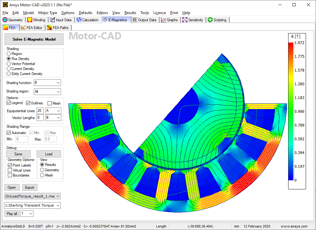
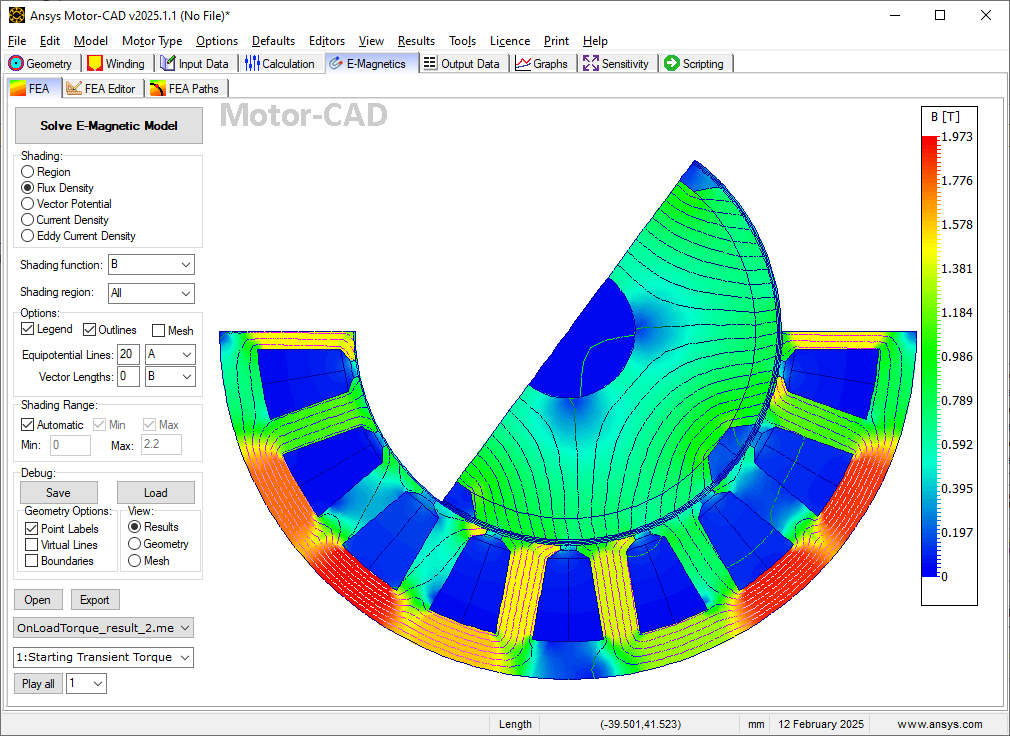
      This is an example with the default BPM model in Motor-CAD, with 2 skew slices (at +-2.5 degrees):

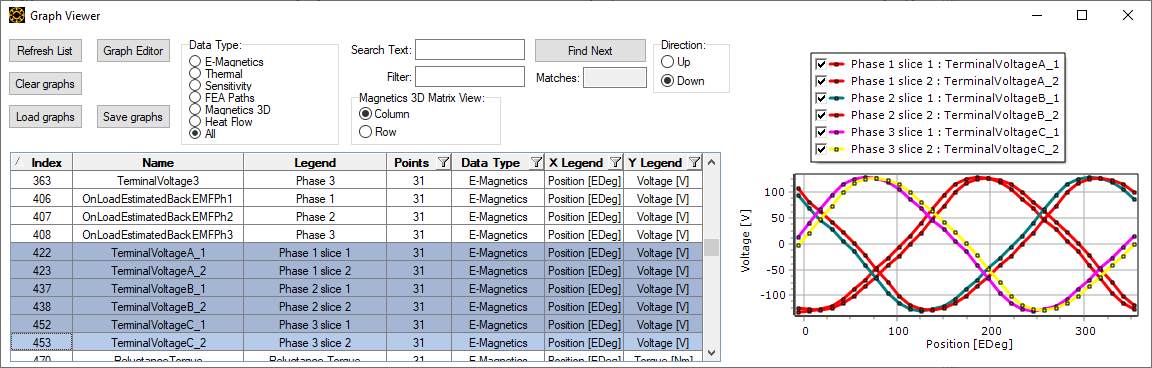
      If you want to see the individual slice results for other results (for example the terminal voltages), the graph data is normally available in the graph viewer. For example here you can see the terminal voltages are slightly shifted between slice 1 and 2:

      You will be able to see the FEA results independently for each slice, which will also show the rotor angle difference between slices, in this case the initial step of the transient (on load torque) calculation, where you can see the different rotor slice angle at the same timestep.

      • matthew.crossley
        Subscriber

        Thanks James, that's a really useful reply and exactly what I needed!

Viewing 1 reply thread
  • You must be logged in to reply to this topic.
[bingo_chatbox]