-
-
July 18, 2023 at 8:31 am
AK
SubscriberHello,
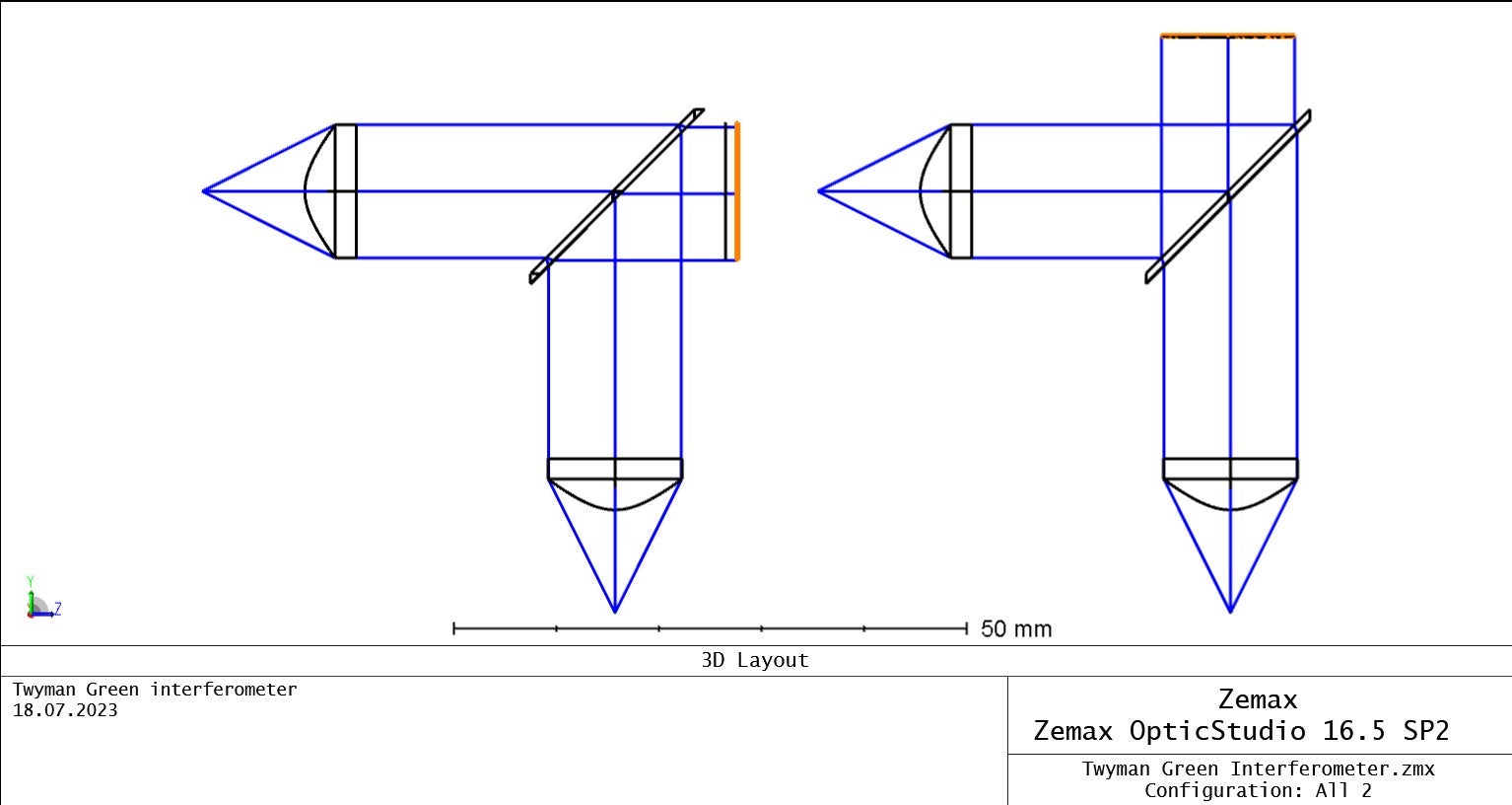
I'm struggling with interferogram calculation in Zemax (used in sequential mode). I red the manual but still have more questions than aswers. As far as I can see, the interferogram is calculated in the exit-pupil. Please correct me when I'm wrong. So…
…how can it be, that I can choose different surfaces? What kind of calculation is used when you switch the surface? POP or raytracing?
…how can it be, that you can choose "image" as surface in the case shown below (modified Twyman Green file out of the sample directory). The image surface is conjugated to the point source, so you don't have a interferogram in the image-layer.
I can't find anything helpful in the manual. Please help, thanks!
Best regards
Andre
-
July 18, 2023 at 9:32 pm
Guilin Sun
Ansys EmployeeCurrently please post your questions to Zemax community here Connect with your fellow Zemax-ers | Zemax Community as Zemax has not fully migrated to this forum yet. Sorry for any inconvenience.
From my knowledge, the image plane should be conjugated with the exit-pupil, not in its focal plane.
-
- The topic ‘Calculation of interferogram (in sequential mode)’ is closed to new replies.


-
3407
-
1057
-
1051
-
896
-
882

© 2025 Copyright ANSYS, Inc. All rights reserved.


