-
-
June 6, 2023 at 5:51 am
Hrushi
SubscriberCan anyone tell me about contacts and boundary conditions while doing static analysis of ball bearing. I am facing some errors.
-
June 6, 2023 at 7:56 am
Nanda
Ansys EmployeeHello Hrushi,
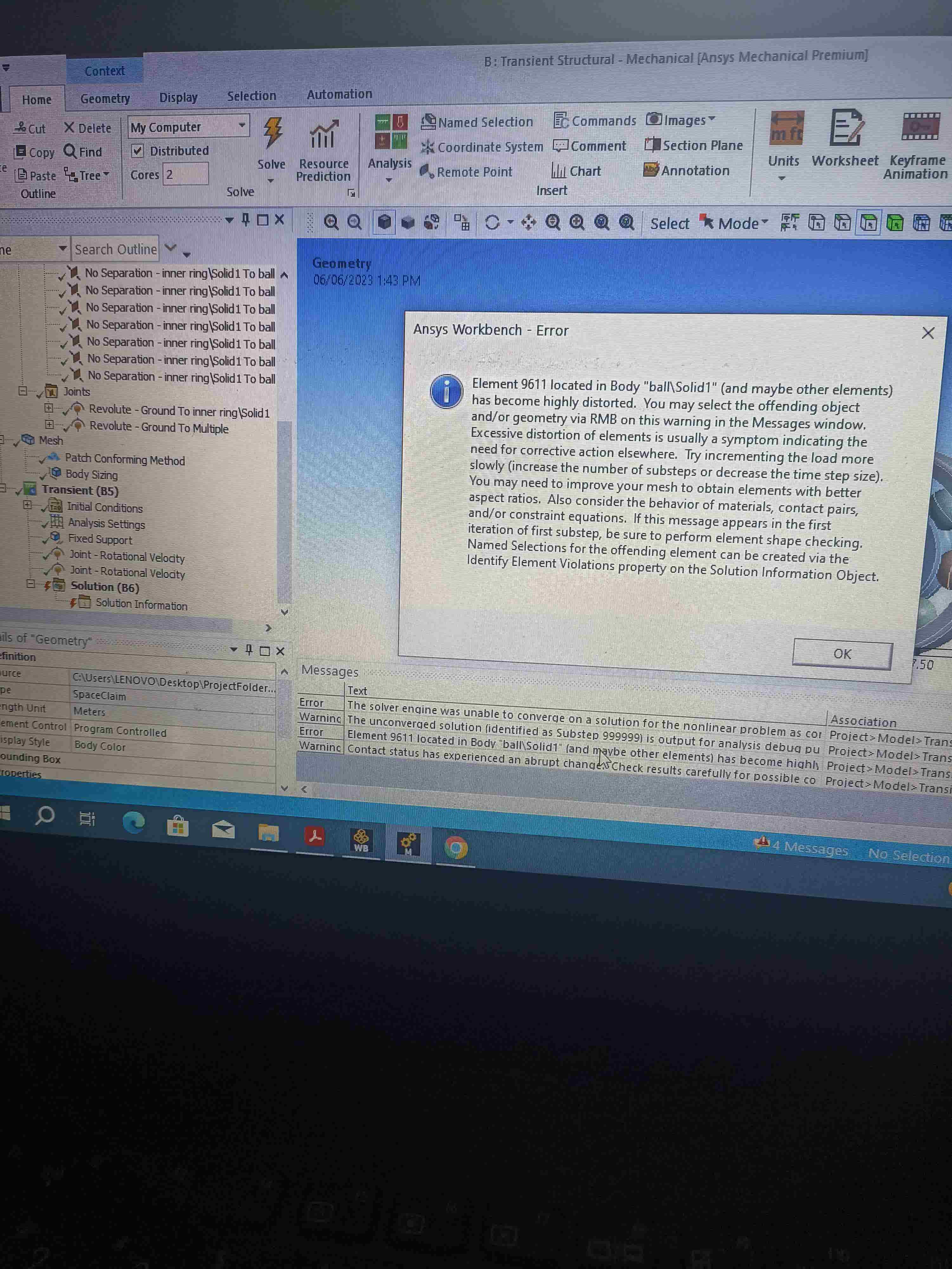
If you're working on a geometry similar to this, by default ansys generates several bonded contact between bodies. Make sure you change them to "No separation". Because this contact definition allows frictionless sliding, but the bodies will not separate.
Â
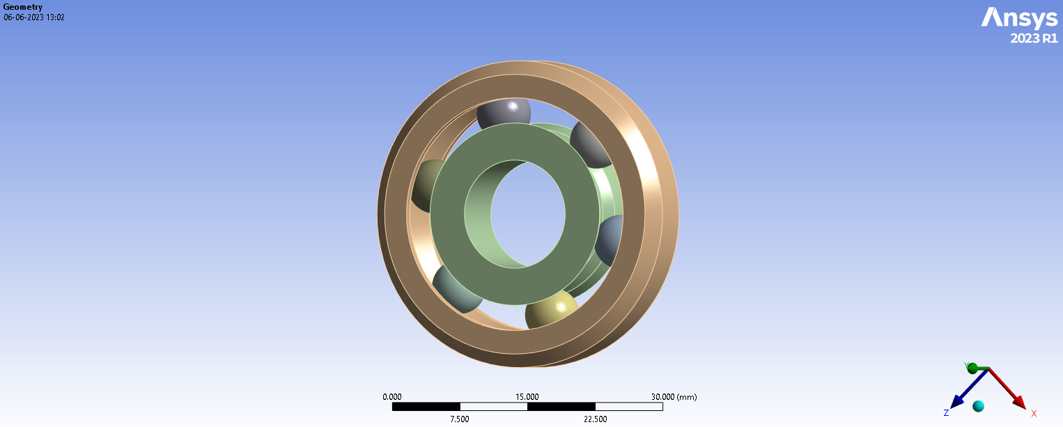
What is the end goal of your project? Let's assume you want to keep outer ring stationary and rotate the inner ring and you want to capture stresses developed. For this workflow, if I were you, I would prefer Transient structural than Static structural. I would also turn on large deflections to on and will setup my time controls manually. Coming to your boundary conditions question, you need to assign revolute joints scoped "body to ground" for any of the side face of inner ring and and also another revolute joint scoped "body to ground" for all balls. Can we know more about the errors you're facing? Do try checking the forum discussions with error messages you're facing, if they are not available in the forum, do share those screenshots here for a better understanding.
Here are some Ansys help links related to the contacts and boundary conditions:
Definition Settings (ansys.com)
14.5.3.1. Rolling Bearing - Analytic (ansys.com)
Regards,
Nanda.
Guidelines for Posting on Ansys Learning Forum
How to access ANSYS help links
Â
Â
-
June 6, 2023 at 8:14 am
Hrushi
SubscriberI want fatigue life.Â
-
June 6, 2023 at 8:17 am
-
June 6, 2023 at 9:04 am
Nanda
Ansys EmployeeHello Hrushi,
This is a bit strange error to occur in this analysis, if you have linear material properties only. The above message is often observed when elastic-plastic material properties are defined within the model, what are the materials assigned to your model?
Here's how I would debug this error:
- Check the stress values at the last converged step and compare this to the yield stress and ultimate stress defined in ANSYS material library. If the observed stress is above the yield stress and approaching to the ultimate stress, then this indicates that the model probably is approaching or is at failure limit.
- Make sure large deflections are set to on.
- I would also play with mesh settings and refine them if required.
- I would apply the load slowly by increasing substeps and also time steps (if required).
Hope this helps.
Regards,
Nanda
-
June 6, 2023 at 9:22 am
Hrushi
SubscriberStructural steel
-
June 6, 2023 at 9:41 am
Nanda
Ansys EmployeeHello Hrushi,
Then the problem might be due to insuffient constraints, I would suggest you to try the steps in my previous response. I don't think contact penetration causes this issue, but I would check for any initial penetration through contact tool. I would allow the solver by giving time to deal with this initial penetration, without giving any loads in first time step. I would change my global mesh settings to linear, as linear elements are less susceptable to mesh entanglement than quadratic elements. Also, try hex dominant method instead of patch conforming in mesh settings, hope this resolves the issue.
Method Controls and Element Order Settings (ansys.com)
The Fundamentals of FEA Meshing for Structural Analysis (ansys.com)
Â
-
- The topic ‘Ball bearing’ is closed to new replies.
-
6379
-
1906
-
1457
-
1308
-
1022
© 2026 Copyright ANSYS, Inc. All rights reserved.

