TAGGED: ansys-aqwa, aqwa, workbench
-
-
February 21, 2024 at 5:03 am
r.abbasi
SubscriberHello,
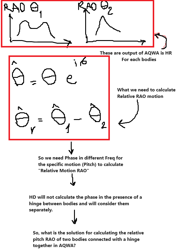
Recently, I obtained a Relative Amplitude Operator (RAO) of 2 dependent bodies (which are connected with a hinge) in pitch motion, in the Hydrodynamic Response to irregular waves, which aligns with previous works. However, calculating their Relative Pitch RAO is not as straightforward as subtracting RAO of body 1 from RAO of body 2. This is because the phase needs to be taken into consideration, and the output RAO for each component does not include the phase information. Consequently, I am unsure how to determine this phase(I mean complex and imaginary parts of motion).
There is a phase component in the Hydrodynamic Diffraction part labeled as RAO phase, but I am uncertain whether this is what I require. Additionally, even if it is, the frequencies associated with it do not match or align with the frequencies of the Hydrodynamic Response part.
I would appreciate your assistance in finding a solution to this issue.
-
February 22, 2024 at 12:01 pm
Shuangxing Du
Ansys EmployeeHydrodynamic DIffraction (HD) does not directly include the hinge joint effect. If you want the RAOs of the structures with the higne effect in HD, please define the equivilent connection stiffness matrices between the two structures, then run HD.
To have the motion reference point to be shifted to a common location for the relative motion RAOs of the hydrodynamic interaction structures, the phase shifting for all the motion DOFs could be calculated by
k[(X_ref - X_cog)cos(dir)+(Y_ref - Y_cog)sin(dir)]
where k is the wave number, dir is the wave direction, (X_ref, Y_ref) is the common point, (X_cog, Y_cog) is the horizontal position of a structure.
-
February 22, 2024 at 4:18 pm
r.abbasi
SubscriberThank you for your response. i think I didnt ask my question clearly.
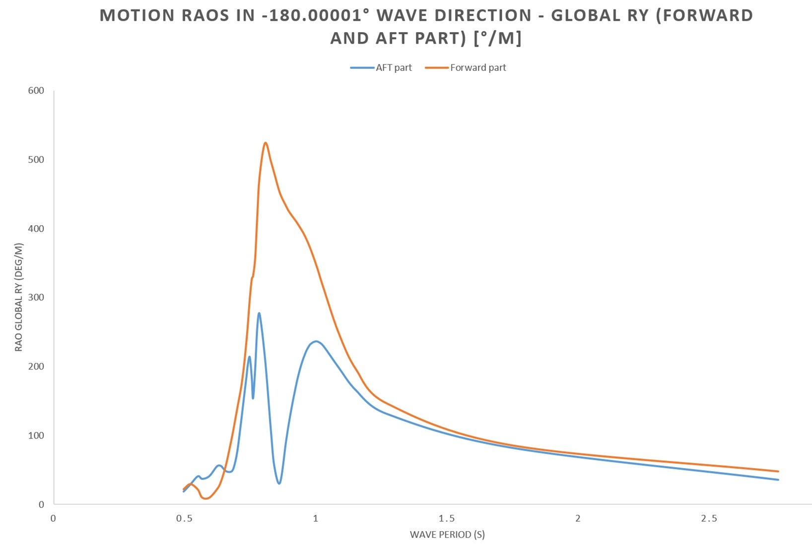
the RAO that I have attached is the pitch RAO of 2 bodiies which are connected with hinge.
for calculate the Relative Pitch RAO, I need the complex RAO,I mean this RAO is not with consideration of their phase.
(Complex motiion and real part)
thank you
-
February 22, 2024 at 4:44 pm
Shuangxing Du
Ansys EmployeeThe results you showed are the RAO amplitudes. You can also output the RAO(phase) for the phases of RAOs. With these two sets of data, the real and imaginary RAOs can be calculated, i.e.
RAO_real = RAO(amplitude)*cos(phase)
RAO_imag=RAO(amplitude)*sin(phase).
-
February 26, 2024 at 7:56 am
r.abbasi
SubscriberHello,
Thank you for your explanation. I have compared the RAO of each body with the literature, and my results show validity with errors of less than 5%. However, when calculating the Relative Pitch RAO, the errors have increased, and the root cause appears to be the phase difference between bodies.
As I comprehend, there is only one RAO phase vs. frequency in the Hydrodynamic Diffraction part. However, the frequency of this part does not align with the frequency of RAO motion in the Response part. How can I determine the exact frequency difference to match the frequency in the Response?
Thank you.
-
February 26, 2024 at 9:31 am
Shuangxing Du
Ansys EmployeeThe phases of the RAOs output in Aqwa are the values with respect to each structure's COG. If you need to have the relative Pitch RAOs between two structures, you may need to shift the motion phases with respect to a common point, for example the COG of the fisrt structure.
If you want to compare the Hydrodynamic Diffraction analysis's RAOs with the time domain results, you may need to include the mooring and/or joint effects in the Hydrodynamic Diffraction analysis by defining the equivalent structural connection stiffness matrix. In Hydrodynamic Response with the Analysis Type of Time Domain Response in Regular Wave, you can define an Airy wave with a small wave amplitude, the time domain responses divided by the wave amplitude should be close to those from the Hydrodynamic Diffraction analysis, if there is no non-linear drag force defined.
-
February 27, 2024 at 12:23 am
r.abbasi
SubscriberYour explanation is clear, but I'll make a few adjustments for clarity:
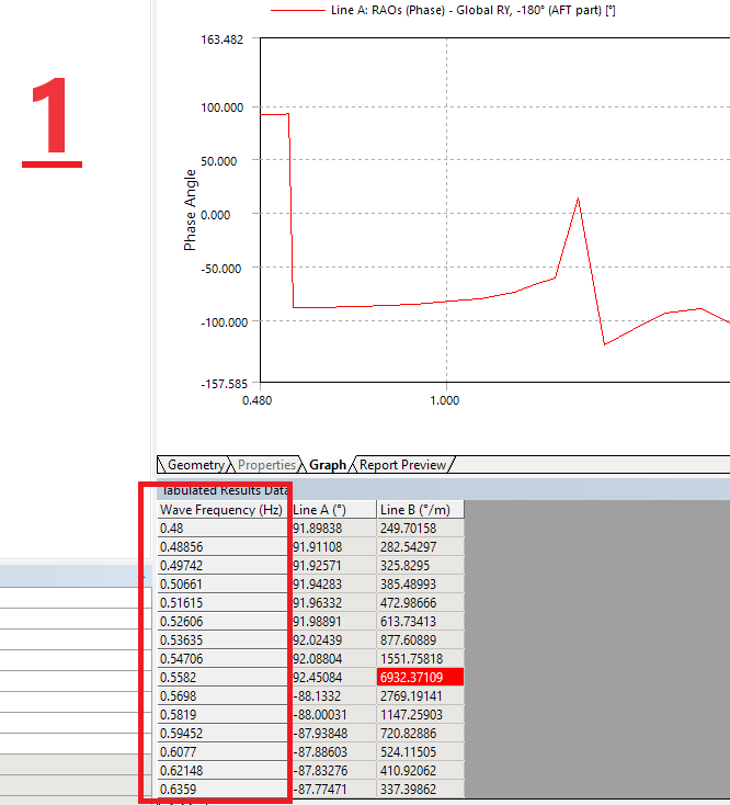
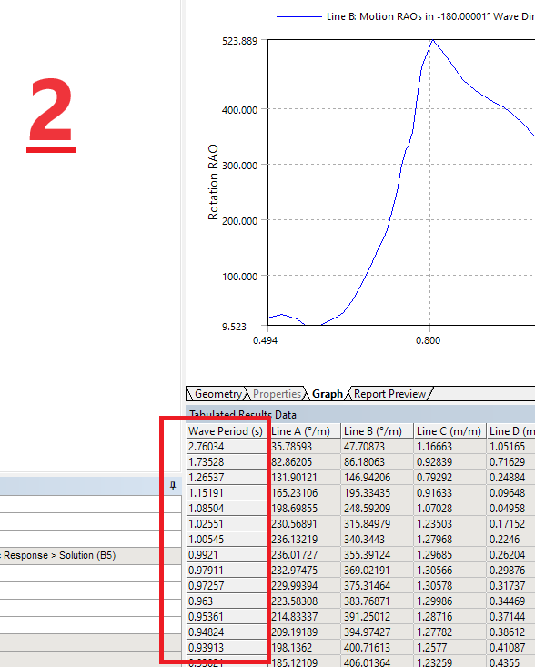
Thank you for your explanation. I have attached two images: the first one displays the range of frequencies with RAO phase in Hyd_diffraction, and the second one shows the frequency range in Hyd_response. For each body, I have "RAO phase Angle" (hyd_diffraction) and "Rotation RAO" (hyd_response).
Currently, my results in "Rotation RAO" align correctly with the reference. However, when I calculate the Relative Rotation RAO by considering the phase Angle, the output is incorrect. Consequently, the issue seems to be related to the "RAO phase Angle."
Now, I have two questions:
Is there an alternative solution to calculate the phase Angle for each body?
If the RAO Phase Angle is the only way to calculate the phase, how can I ensure that the computation frequencies align exactly with the frequencies in RAO motion in Hyd_response?
thank you
-
February 27, 2024 at 8:02 am
r.abbasi
SubscriberAlso, you mentioned that If you want the RAOs of the structures with the higne effect in HD, define the equivalent connection stiffness matrices between the two structures, then run HD!!
I am aiming to determine the phase angle of each body at each frequency. However, the RAO_phases output in HD is not applicable for two structures connected with a hinge because the hinge is not considered in the analysis.
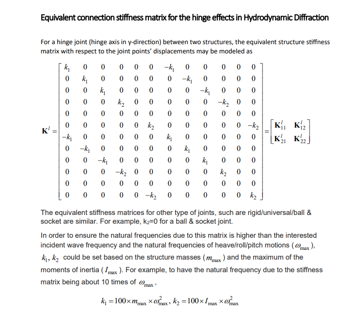
How can obtain RAO_phases in AQWA for two bodies connected with a hinge? If stiffness matrices are required, how can they be calculated and incorporated into the analysis?
-
February 27, 2024 at 1:59 pm
Shuangxing Du
Ansys EmployeeI am sorry that the frequency integration points in the frequency hydrodynamic responses are automaticaly selected by the program to ensure the accuracy of the spectral integration, of which the frequency intervals are refined near the structures' natural frequencies and the peaks of the wave spectra.
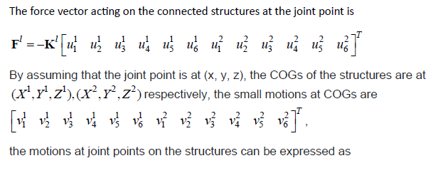
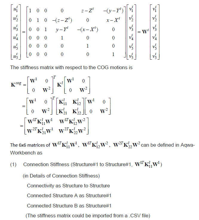
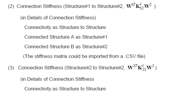
Please see a recommendation on how to create an equivalent connection stiffness matrix for two structures are linked by a hinge in y direction.
-
February 27, 2024 at 2:40 pm
r.abbasi
SubscriberThanks for your response. So it seems we have to calculate the equivalent stiffness based on the hinge and damping, and then import or put values as a stiffness matrices in HD.
there isnt any way to get and have a matrices as a output in AQWA?
-
February 27, 2024 at 3:09 pm
Shuangxing Du
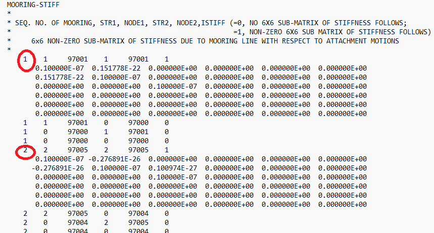
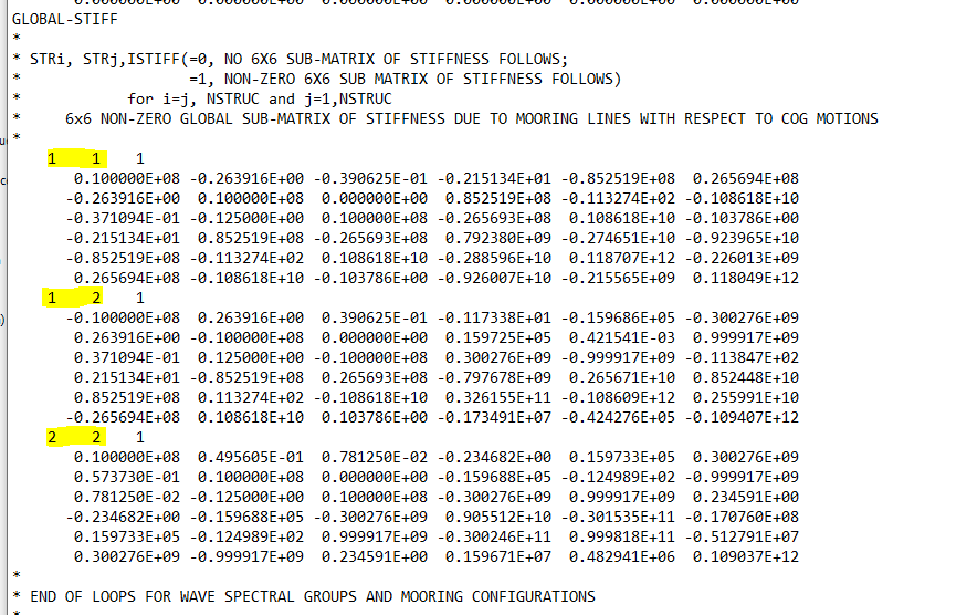
Ansys EmployeeWe have not tried. But it could be possible to replace the hinge by two zero inital length linear mooring lines with the attachment points on the hinge axis, then to run Hydrodynamic Response with the analysis type of stability analysis, the mooring stiffness matrix can be output in the .MFK file.
-
February 28, 2024 at 3:29 am
r.abbasi
SubscriberThanks again for your explanation. I followed your instructions and replaced the hinge with two zero initial length linear mooring attachment points on the hinge axis, as shown in the attached photo.
Afterwards, I retrieved the data from the.MFK file, which included two matrices allocated for each structure. However, I'm unsure which one I should use for additional matrices(??), as shown in the attached photo.
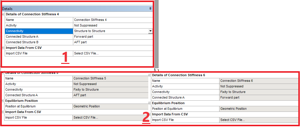
Following your guidance, I defined the connection stiffness in two conditions: first, structure-to-structure, and second, each structure to fixity, as illustrated in the attached photo.
Despite these efforts, the results were consistent across all situations. Even in the pressure and motion sections in hydrodynamics (HD), it indicates that each part becames separate.
-
February 28, 2024 at 9:39 am
-
March 4, 2024 at 1:21 pm
r.abbasi
SubscriberThank you, but I have already attempted that, and the results are not logical. This is because the hinge and its specific damping are being replaced with a stiffness(although bodies take apart again)!
As a result, AQWA cannot accurately capture the 'Angle Phase' of two structures connected with a hinge, while also considering the hinge (or other joint).???
-
March 4, 2024 at 2:05 pm
Shuangxing Du
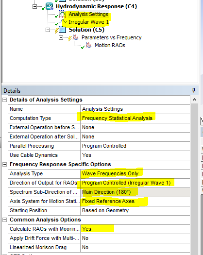
Ansys EmployeeIf you need to include the hing damping, you may have to use the Hydrodynamic Response with the Computation Type of Frequency Statistical Analysis. In this analysis, the hinge effect (including the hinge damping) is automatically included.
If the RAOs at wave direction of 180 degrees are required, please define a wave spectrum and set the wave direction as 180 degrees.
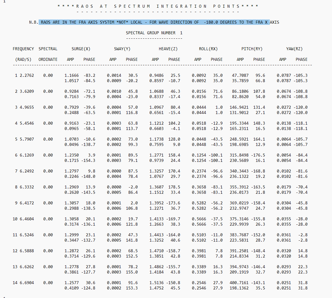
Then in the analysis output FREQUENCY.LIS file which is stored in (your project)\dp0\AQW-2\AQW\AQ\Analysis, the RAO amplitudes and phases at the wave spectral integration frequencies are listed as
Note that the RAOS are with the fixed reference axis system, the relative pitch RAOs could be the differences of the real/imaginary parts of the pitch RAOs of the two structures.
-
March 5, 2024 at 2:54 am
r.abbasi
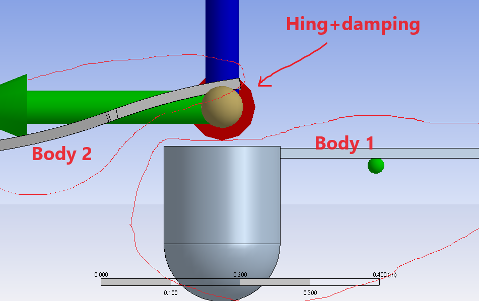
SubscriberThanks again for your clarification. For further reference, I have included a picture of the recent dynamic analysis of two bodies connected with a beam. There is no mooring involved. I intend to calculate the relative pitch motion RAO, which requires having a phase difference between the two bodies at each frequency with the presence of the hinge.
Structure and dynamic of bodies:
To be more clear check bellow please:
I did the same procedures as you mentioned, but I couldn't find two bodies RAO( I mean there isn't separate bodies RAO there with that title)!! to see if it will work or not!
-
March 5, 2024 at 9:35 am
Shuangxing Du
Ansys EmployeeIt is confirmed that RAOs in the line with frequency and specral ordinate values are the RAOs of the 1st structure, followed by other structure(s). The unit of RAO phases is in degree and the unit of the rotational RAO amplitdues is in degree/m.
-
- The topic ‘AQWA :relative pitch RAO of two dependent parts’ is closed to new replies.


-
4678
-
1565
-
1386
-
1242
-
1021

© 2025 Copyright ANSYS, Inc. All rights reserved.

