

TAGGED: ansys-maxwell, current-excitations, maxwell, maxwell-2d
-
-
January 23, 2021 at 2:01 pm
ruhanj
SubscriberHello friends,
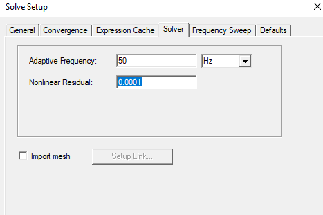
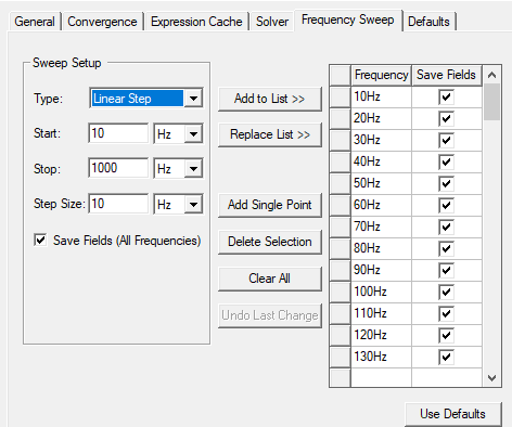
I just became a member of this platform. I want to ask you a topic that confuses me. I designed a simple 2D model and excite 140 kA to conductor1. I did not apply any current to conductor2 and I want to find out how much amper conductor1 will create on conductor2. For this I work on eddy solver. I have assigned copper on my two conductors. Adaptive frequency is 50 Hz. When I examine the results, I find it correct that the current flows in the opposite direction of the conductor 2, but when I examine the current density, its amplitude is almost the same as the conductor1. Is this result true? If you think it's wrong, where am I making a mistake. Can you help me? In addition, by which formula can I verify my work?
January 24, 2021 at 5:01 pmSubscriberI'm waiting for your answers, thanks for your help.nJanuary 25, 2021 at 12:53 pmNavya Chode
Forum ModeratorHi,nFor this simulation, you should see a high current density in conductor 1 compared to conductor 2. nI did see some difference in current density, and it seems to be correct, and it all depends on the amount of current you are assigning and the distance between them.nHow did you set up your model?nPlease elaborate on the way you modeled it and plotting the results along with dimensions of conductors and excitation settings. So that I can understand the problem better.nnRegardsnNavyanJanuary 25, 2021 at 5:43 pmSubscriberHi Navya,n First of all thank you very much for your help. Informations are below.n


 n
n n
n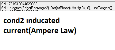
 RegardsnRuhann
Viewing 3 reply threads
RegardsnRuhann
Viewing 3 reply threads- The topic ‘Induced Current’ is closed to new replies.
Innovation Space Trending discussions
 Top Contributors
-
peteroznewman
 5824
5824 -
scabo
 1906
1906 -
Dennis Chen
 1420
1420 -
javat33489
 1305
1305 -
Shyam Prasad V Atri
1021
Top Rated Tags
© 2026 Copyright ANSYS, Inc. All rights reserved.
Ansys does not support the usage of unauthorized Ansys software. Please visit www.ansys.com to obtain an official distribution.
-


