-
-
April 4, 2020 at 1:35 pm
-
April 5, 2020 at 10:14 pm
Karthik Remella
AdministratorHello,
You could try to create an iso surface of your volume fraction (say 0.5). Since your simulation is 2D, it will give you a curve. If you plot the y-coordinate of this curve, you should get the film thickness (in some form - might require additional manipulations depending on your position of the origin).
Please test this and let us know.
Thank you.
Best,
Karthik
-
April 6, 2020 at 3:33 am
-
April 6, 2020 at 4:11 am
Prudviraj
Subscriber
Dear sir, yesterday I read this attached image and how they measured in CFD POST......Can you please elaborate on how to find film thickness over the cylinder at various angles using CFDPOST with the similar approach I have attached...
Your support will be appreciated......
Â
Â
Â
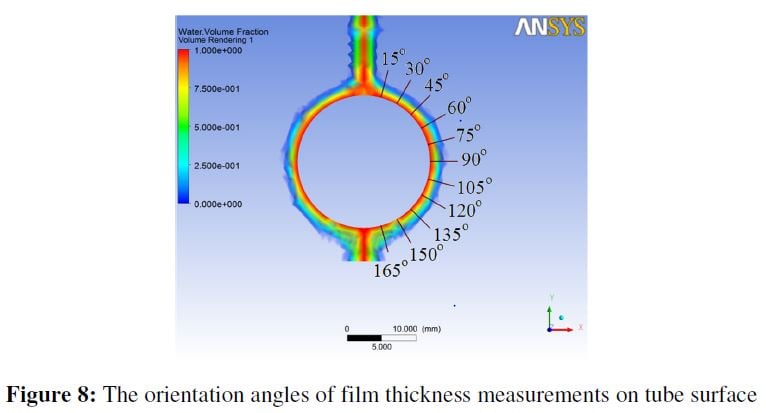
The corresponding mass flow rate to its velocity inlet is then recorded when a proper film
distribution is achieved in simulation result. The thickness of water sheet film on tube surface
is then measured based on angles of 15°, 30°, 45°, 60°, 75°, 90°, 105°, 120°, 135°, 150°, and
165° as shown in figure 8. These angles have been set as a reference values in accordance with
many previous references. The numerical results have been analyzed in CFD-Post
where 4 mm length of measurement lines were positioned normal to tube surface. These
measurement lines acted as a parameters that measures water film thickness at specified angles
as shown in Fig
The thickness of water film are extracted and plotted in a graph of thickness versus orientation
angles. Each measurement data is measured by taking into account the difference of water
volume fraction length which only 1.
-
April 6, 2020 at 5:20 am
Amine Ben Hadj Ali
Ansys EmployeeYou create rakes or lines over each line you use a user variable with 4*alpha phase 2 * alpha phase 1. -
April 9, 2020 at 2:43 am
Prudviraj
SubscriberDear sir, please suggest how to create radial rakes for every 30-degree angle over the cylinder...
-
April 9, 2020 at 8:00 am
Amine Ben Hadj Ali
Ansys EmployeeYou do them manually by providing the starting and end point which corresponds to 30° intervals or via script. Either in Fluent or in CFD-Post.
If you have EnSight you can ise "By constant on part sweep" method which you can then easily create a sweep in the Theta direction.
-
May 1, 2020 at 10:44 am
Prudviraj
Subscriber -
June 15, 2020 at 4:28 pm
fit78
SubscriberAlternatively, you can generate a polyline from the water fraction contour. Choose the contour level you see fitting the fluid film.
Once you generated the polyline, generate an XY plot. You will get something like this
Then you can export the XY plot and open it in a spreadsheet.
By using X^2+Y^2=R^2, you can find the R which is the distance of the fluid film from the center axis.
Easily, you may find the thickness by substracting the radius of the cylinder you were working on from the R value.Â
To find the location of the film thickness, just use trigonometry since you already have the X and Y location.
Hope this helps.
Fit
-
- The topic ‘How to create isosurface and rakes to find film thickness over the cylinder’ is closed to new replies.
-
4858
-
1587
-
1386
-
1242
-
1021
© 2026 Copyright ANSYS, Inc. All rights reserved.


