TAGGED: dynamic-mesh, interface, sliding-mesh
-
-
February 6, 2025 at 11:20 pm
Mahmoud Nassar
SubscriberHello everyone,
I am working on a 2D turbine in Ansys. I have a rectangular domain divided into four subdomains: front domain, mid domain, rotational domain, and rare domain. The rotational domain is inside the mid-domain.Â
I am trying to simulate the rotation of the turbine while having the mid-domain move back and forward using specific frequencies.
To do so, I am using a sliding mesh to force the rotation of the turbine while using the dynamic mesh to force the movement of the mid-domain using UDF.
My problems are,Â
1- When I try to force the movement of the mid-domain, for some reason the domain moves alone and breaks all the interfaces. The rotational domain (sliding mesh does not follow the mid-domain). The front and rare domains are not deforming to account for the mid-domain movements. How to fix this issue?
2- The turbine is rotating around the origin. If the turbine is going to move back and forward according to the mid-domain movement. How can I track the moment around the moving point (center of the turbine)?
Thanks in Advance -
February 7, 2025 at 3:05 pm
Federico
Ansys EmployeeFor 1), you can specify that the sliding mesh motion is relative to a specific cell zone (mid-domain). That way, as mid-domain moves back and forth, the rotational domain should follow, while still rotating locally.
-
February 7, 2025 at 4:55 pm
Mahmoud Nassar
SubscriberThank you for your reply.
I will try that but I still have a problem with the mid domain movements. I define the mid domain as rigid body. For the rare and front I define them either stationary or deforming. However, when ever mid domain moves it breaks the interfaces and moves alone. Not connected to any domain any more.Â
how to solve that?!what should I define to allow the mid domain motion while keeping the interface intact and make the other domains deform to account for the motion ???
-
February 7, 2025 at 7:09 pm
Federico
Ansys EmployeePerhaps a screenshot showing your domain would help us troubleshoot this.
But if you have mesh interfaces separating mid domain from rare/front, you will need so set both sides of the interface in motion. They are separate zones, so if you don't do this, you will see exactly what you describe.
Only set zones that are truly not moving as Stationary.
Â
-
-
February 9, 2025 at 12:08 am
-
February 16, 2025 at 7:13 pm
Mahmoud Nassar
SubscriberTo address the issues I mentioned earlier, I am utilizing an overset mesh approach. Yet, I am encountering new problems.Â
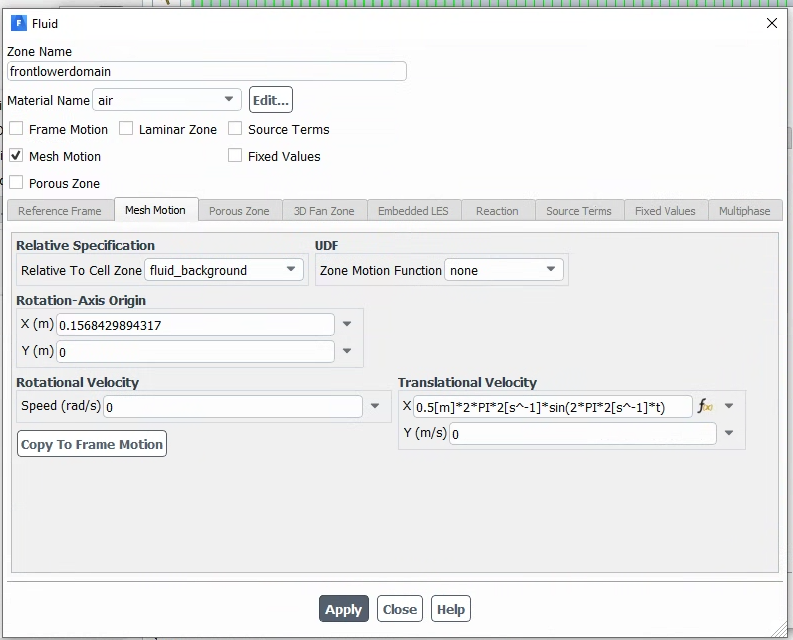
In the overset mesh, I defined three domains for the blades and a background mesh. Inside the zones of each blade, I define transition motion in the x-direction using expression and I define the rotational speed as a constant value. All the blade zones will be defined relative to the background to allow the rotation center to move only in the x-direction otherwise for some reason the rotation axis will move in y and x-directions.ÂNow the problems are:
1- How can I track and write in every time step the position of the rotation axis to validate the motion and calculate the turbine torque around the moving center?2- In wall BCs, I want to define the wall of the blade as moving walls in rotation and transition. How to do so??
Â
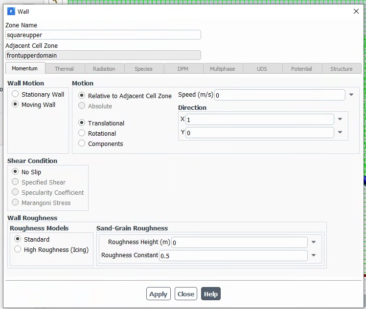
Now in boundary condition where I have to specify the wall, Â
-
- You must be logged in to reply to this topic.
- How do I get my hands on Ansys Rocky DEM
- Unburnt Hydrocarbons contour in ANSYS FORTE for sector mesh
- convergence issue for transonic flow
- Facing trouble regarding setting up boundary conditions for SOEC Modeling
- Point exception in erosion calculation
- Errors with multi-connected bodies using AQWA
- Script Error Ansys
-
2537
-
933
-
787
-
599
-
591
© 2025 Copyright ANSYS, Inc. All rights reserved.