Ansys Assistant will be unavailable on the Learning Forum starting January 30. An upgraded version is coming soon. We apologize for any inconvenience and appreciate your patience. Stay tuned for updates.
Electronics

Electronics

Topics related to HFSS, Maxwell, SIwave, Icepak, Electronics Enterprise and more.

HFSS Simulation Erratic S-parameter results

    • cweave31
      Subscriber

      I am trying to design a waveguide-to-microstrip transition for Ka-band operation, but my simulation results give me some very poor looking results as shown in the attached picture. Would this be considered resonance? Or have I improperly defined my wave ports and/or boundaries? I haven't been able to find a solution for this, meaning I don't know if it is a design issue or a simulation setup issue. has anyone ever seen something like this?

       Ka-Band Waveguide to Microstrip Transition S-parameter Results

    • Praneeth
      Ansys Employee

      Hi,

      Thank you for reaching out to the Ansys learning forum.

      Please provide more details to help us serve you better:

      1. Are you explicitly defining any surrounding region around the microstrip portion of the model?
        If not, please add surrounding space and a proper absorbing boundary as the microstrip has fringing fields over the top surface.
      2. Please see if the transition between the waveguide to microstrip is modelled correctly.

      If possible please share the screenshots of the model to understand your case better.

      Best regards,
      Praneeth,
      Click here to join Electronics Community and build a network. 

    • cweave31
      Subscriber

      Hi Praneeth,

      Thank you for your answer.

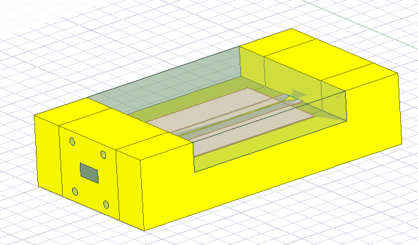
      I've defined a region of air around the microstrip. I have left the boundaries as default. Should these be changed to absorbing boundaries? What if I want to put a cover over this section? 

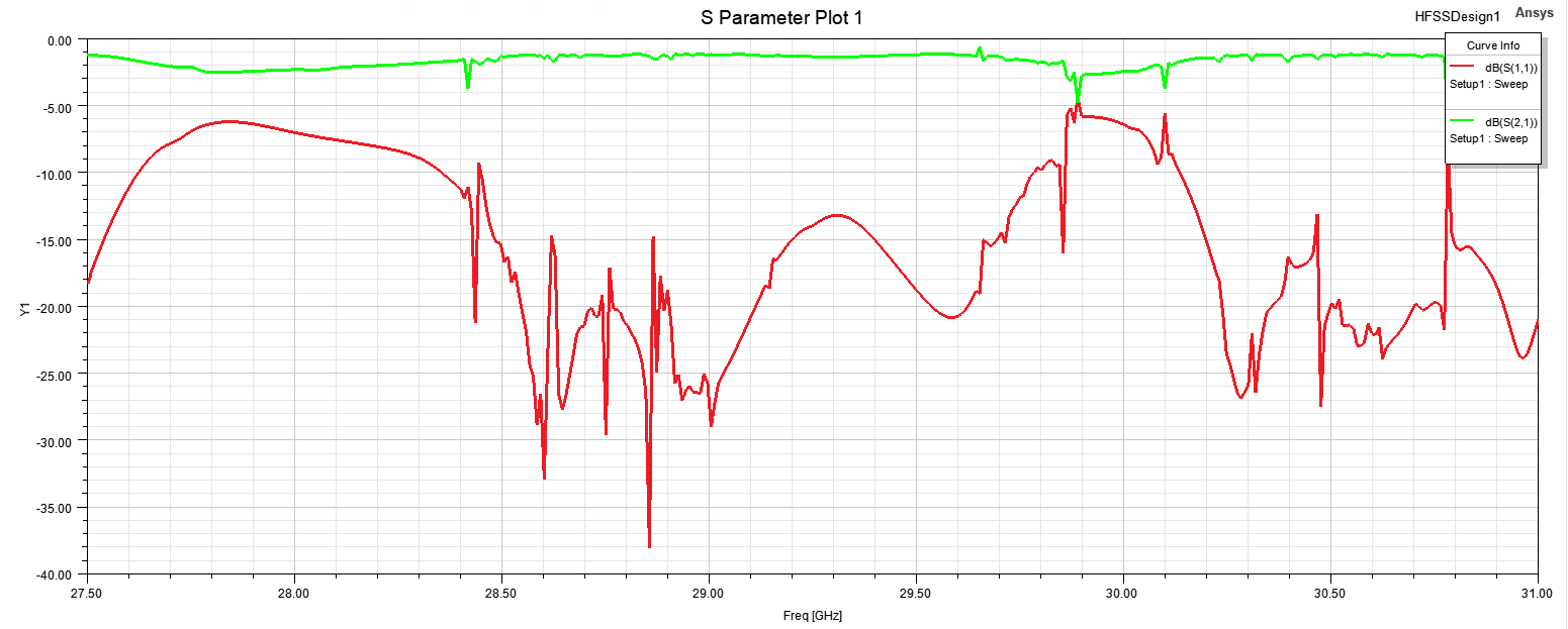
      Is what I'm seeing in the previous simulation due to resonances caused by the fringing microstrip fields and the PEC around the air region?

      I've attached a picture of the waveguide to microstrip transition for reference. 

    • Praneeth
      Ansys Employee

      Hi,

      Please note that the default surrounding region is PEC in Ansys HFSS. So, check the response after applying any of the absorbing boundary conditions to the faces of the air region. I cannot confirm the exact reason for this response with the details available. If you have support access, then please raise a request so that the model can be examined.

      Best regards,
      Praneeth.

    • Monito
      Subscriber

      Did you figure out the problem? Im having the same issue.

Viewing 4 reply threads
  • You must be logged in to reply to this topic.
[bingo_chatbox]