Hello Javat,
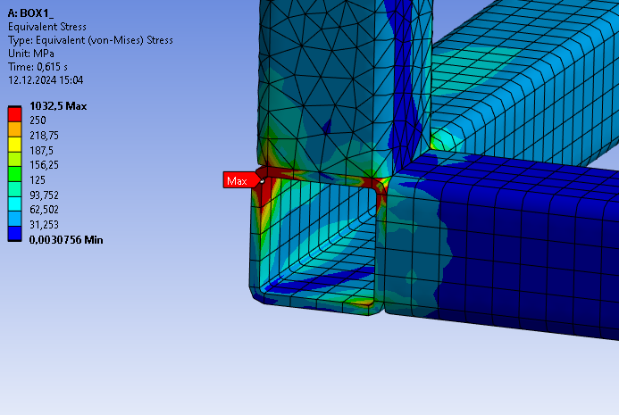
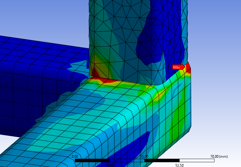
Your model shows three square tubes coming to a corner with bonded contact to hold them together.
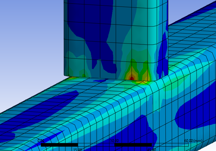
This model is a simplification of reality, and is useful to look at overall stiffness of the frame structure. It is also useful to look at stress along most of the tube length if you ignore the tube ends near the bonded contact for about 2 diameters of the tube. You can call this the System Model. One method to exclude stress results from the ends of the tube is to prepare the geometry in SpaceClaim where you can set up planes 2 diameters from each end to slice the body into two pieces, then use the Share button on the Workbench tab to have the mesh connect the two pieces into one mesh. In Mechanical, make a Named Selection of the tube bodies that are the long middle pieces and don’t select the tube bodies at the ends where the bonded contact exists. That way the plots will not show the unrealistic stresses at the ends.
In reality, the tubes are welded along at least two opposite edges and stress in the welds can be evaluated separately from the finite element model in a hand calculation. Weld strength is evaluated using the average stress in the weld bead throat. The inputs to the hand calculation is the average shear and normal forces in the plane of the weld bead throat. To separate shear and normal forces, you need a coordinate system aligned with the weld bead throat. Average stress is force divided by area. Several national codes specify how weld strength is to be evaluated. The point is the finite element model provides the sum of the shear forces and normal forces going through the weld bead. You don’t need to evaluate stress in the elements of the weld bead.
One simple way to get the forces going through the weld bead is to use a Fixed Joint scoped to the edge on one side of the tube, and a matching length of corner edge of the mating tube that the weld bead connects. Probe the forces going through the Fixed Joint to get the input values to the weld strength hand calculation. This is only appropriate for a short length of weld bead. It is inappropriate for a long weld bead, where several short lengths should be created to get a local value of force being carried by the weld bead since there is often a higher force near one end of the bead which you don’t want to average away in a long fixed joint.
For other techniques, read this discussion, which has two links of interest.