-
-
December 10, 2024 at 7:26 pmzmvickSubscriber
I have performed a physical tensile test on a unidirectional glass fiber composite material, and I am trying to replicate the results in Ansys using ACP. I cannot get the model to converge at the elongation that I saw in the actual test.
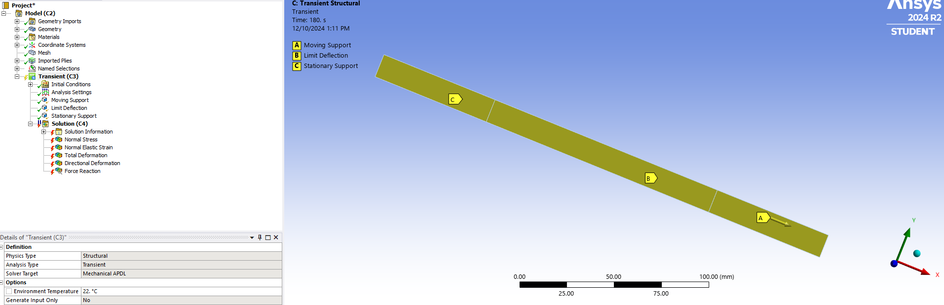
Test specimen is modeled as a surface. The surface is meshed and then imported into ACP. Apply material and plys to a the surface using standard ACP shell mesh method. Note, the material is a custom composite material where I defined materials properties based off the actual tensile test data.
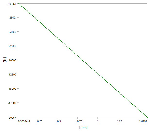
Import the ACP data into a Transient Structural analysis with Large Deflections enabled. The tensile test was performed at 1mm/min. I have fixed one side of the test sample, and I have applied a tabular displacement to the other side to move from 0mm to 3mm over 180sec. The actual samples all failed between 3 and 4mm.
I have tried many different combinations.
- Element type: Program Controlled and Linear.
- Application Based Setting:s Quasi-Static, Low Speed Dynamics, and Medium Speed Dynamics.
- Adjusted the minimum time substep from 0.1 to 0.0001 sec.
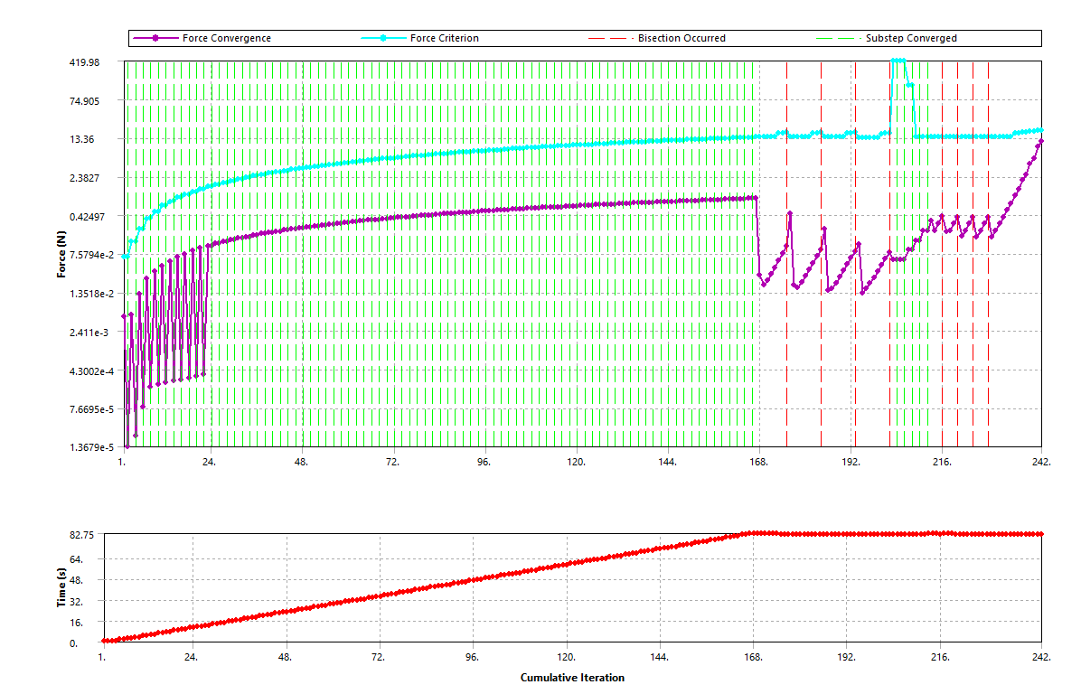
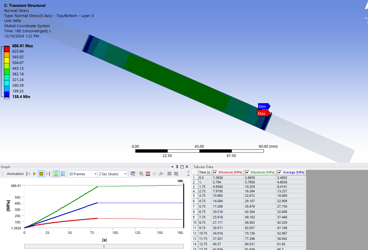
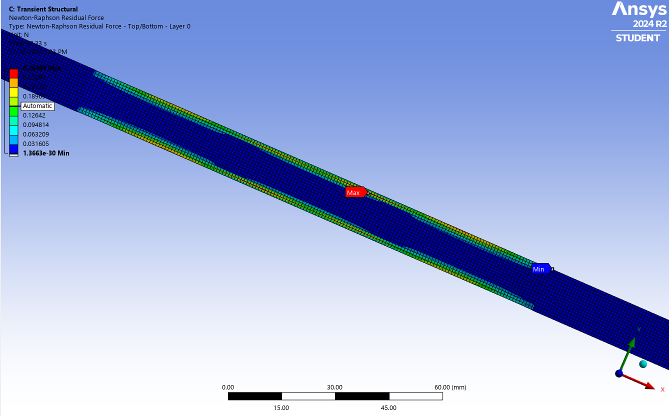
In every case, it stops converging around 90sec or 1.5mm of deflection. The partial result appear to match the test, but I would like to test until that 3-4 mm. I have enabled Newton-Raphson Residual Force plots. They indicate the issues are at the edges of my test specimen. See below.
Sample Partial Results
Newton-Raphson Risidual Force plot
Force Convergence plot from Solution Information
-
December 13, 2024 at 2:10 pmJohn DoyleAnsys Employee
I assume you are including stress stiffening effects with large deflection turned ON. What does the force vs deflection curve look like at the point of convergence failure? Are you losing stiffness resistence across the section? If so, perhaps the nonconvergence is reflecting the onset of a physical instability. In the physical test, how is the test specimen responding to the load at this point? Is there any local damage (i.e. delamination, cracking and/or yielding) beginning to develop? Also, perhaps the FEA element type is not sufficient to capture the local effects at the higher strains. SOLSH190 might be better.
-
December 17, 2024 at 8:38 pmzmvickSubscriber
The output file does note that stress stiffening is on. My displacement vs reaction force graph is very linear all the way through the simulation. (Reaction force is in negative x-direction.)
In the physical specimens, layers did begin to fail right around the 3 mm of displacement. Most had fairly linear force-displacement curves until 3.5 mm or so, and then pretty rapid failure from there. I'm not sure how to change the element type. I am using ACP to model the composite, and ACP only allows the use of surface input geometry. I am then using shell element data in the analysis. I don't know how to use SOLSH190 elements or if it is even possible.
Â
-
- You must be logged in to reply to this topic.
- Error when opening saved Workbench project
- At least one body has been found to have only 1 element in at least 2 directions
- Script Error Code:800a000d
- Elastic limit load, Elastic-plastic limit load
- Element has excessive thickness change, distortion, is turning inside out
- Image to file in Mechanical is bugged and does not show text
-
1882
-
802
-
599
-
591
-
366
© 2025 Copyright ANSYS, Inc. All rights reserved.