-
-
February 12, 2024 at 3:23 pm
Samad Atta
SubscriberHello there,
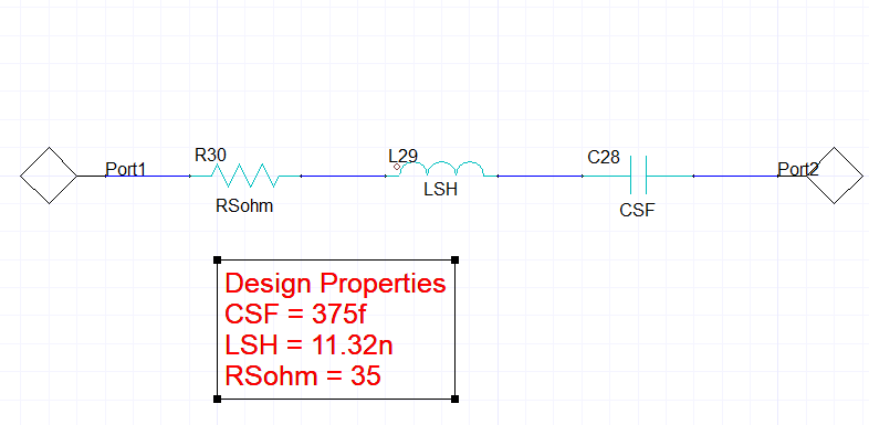
So I designed a series RLC matching network for an antenna in HFSS then I imported the design as a dynamic hyperlink into HFSS circuits where I actually made the matching network. Now in HFSS circuits it's not like AEDT (3D modeller) where if you want to tune you just set your variables as derivatives and tune your plots. within the matching network, I made all the variables for R, L, and C values must be local variables so I don't know exactly how to tune them because I am new to HFSS circuits. I have some images below to give a better understanding, thank you as you get back to me.
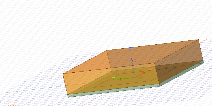
patch antenna from 3-D modeller
matching network:
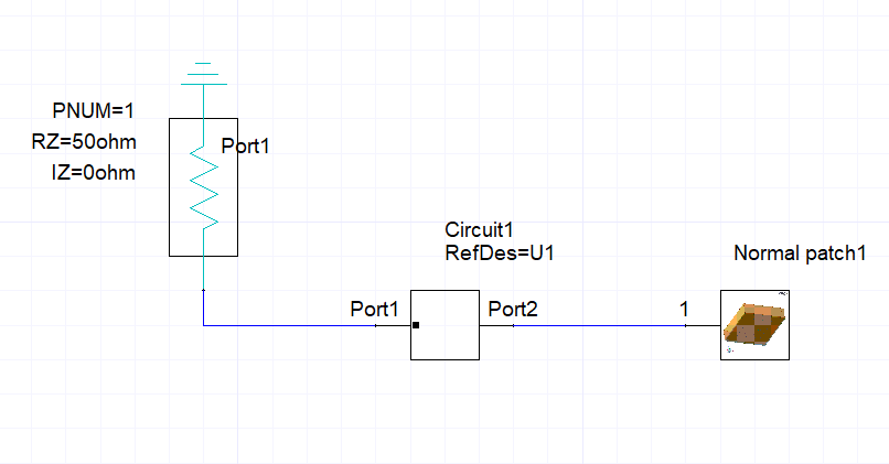
Assembled system:
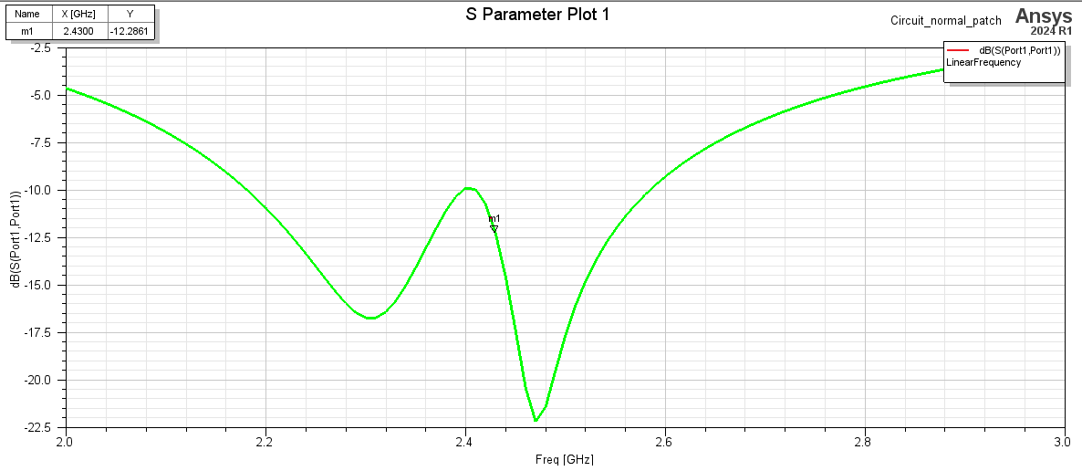
sample results:
i just want to tune my response a bit, thanks!
-
February 12, 2024 at 7:39 pm
Faezeh Ladani
Ansys EmployeeHi Samad,
You can define R, L, C as variables in Cistuit and add a parametric sweep. With this you can see how the response of the matching network changes with respect to R,L,C.
-
February 12, 2024 at 8:04 pm
Samad Atta
SubscriberHello Faezeh yea i know i can run a parametric sweep but it gets tedious when dealing with more than one variable. Tuning is better for this case, thank you though!
-
February 13, 2024 at 1:27 am
Irina G.
Ansys EmployeeHello Samad,
in circuit, one s1p touchstone file represents the HFSS design. You can run Parametric setup in Circuit design with several variations of all 3 variables. It will run very quickly since it will not require to re-run HFSS design.
You can even export S-parameters from HFSS design and import *.s1p file into the Circuit design instead of linkng HFSS design. The circuit design variations run extremely quickly compared to HFSS design. After that, you can use Optimetrics > Tuning to choose the variation closest to wha you need. Also, using Optimization in Circuit design to let Circuit solver (Nexxim) to choose the values of variables is the best option in my opnion. In circuit, there is no Derivatives option similar to the one in HFSS. You can check Sensitivity option under optimetrics if the goal is to report derivatives values, not to tune the variables.
-
February 13, 2024 at 3:46 am
Samad Atta
SubscriberIrina
Thank you for your answer, I just thought it would act like HFSS 3D modeller. You seem to know a lot about HFSS circuit tool so i have a question for you, please is there a way i can just select passive elements and use them in my design? the only way i can have passive elements (resistors, inductors and capacitors) is by having them within my matching network which means any variables i make there will be local variables which means i cant select them for optimization. Thank you as you reply.
-
February 13, 2024 at 11:02 pm
Irina G.
Ansys EmployeeYou can try the steps below; the links are useful if you have time to invest in learning the tools.
BTW, if you start this thread only because you used Matching tool (as in the old trainings) and the results are far from the expected, check if you forgot to perform "Conjugate" command in the very beginning.
'''''''''''''''''''''''''''''
To insert a parameterized circuit component like a resistor in the Circuit design, you can follow these steps as described in the document titled "HFSS 3D Layout — Getting Started - ANSYS Innovation Courses" [1] and "ANSYS Electronics Desktop: Simple Communications Channel For Signal Integrity Analyses - Part I" [2]:
1. From the Component Libraries menu, under Nexxim Circuit Elements, select Resistors.
2. Choose the resistor you want to insert, for example, RES_:Resistor, and drag it into the schematic.
3. Click a second time to place the second resistor in the circuit.
4. Right-click and select Place and Finish to place the resistor.
5. Component values can be changed by double-clicking on the value and editing it. For instance, you can assign the value of 100 ohms to the vertical resistor and 1 G ohms to the horizontal resistors.
Remember, schematic components can be moved by left-click and drag. Components can also be rotated by with Ctrl-R.
References:
[1] Title: "HFSS 3D Layout — Getting Started - ANSYS Innovation Courses", URL: "/courses/index.php/courses/ansys-hfss-3d-layout-getting-started/"
[2] Title: "ANSYS Electronics Desktop: Simple Communications Channel For Signal Integrity Analyses - Part I", URL: "/knowledge/forums/topic/ansys-electronics-desktop-simple-communications-channel-for-signal-integrity-analyses-part-i/" -
February 14, 2024 at 12:03 am
Samad Atta
SubscriberHello Irina,
Thank you for the response again, i was able to just copy the components from the matching network out into the main schematic and then play around with it. I tried your method of putting in normal passive components but the components are not normal...
For instance, the resistor will ask me for resistivity, the capacitor will ask me for a number of turns but i found a way around it. for the tuning I just exported my S1P file to ADS and tuned with series RLC values there then copied those same values to HFSS and I fixed my alignment issue.
Thank you so much Irina.
-
- The topic ‘Tuning with HFSS circuits’ is closed to new replies.


-
3587
-
1193
-
1086
-
1068
-
952

© 2025 Copyright ANSYS, Inc. All rights reserved.


