General Mechanical

General Mechanical

Topics related to Mechanical Enterprise, Motion, Additive Print and more.

Bending moment and shear force diagram

    • Farjad Akram
      Subscriber

      Im fairly new to ANSYS workbench and wanted to know how do I produce a bending moment and shear force diagram for this 3d geometry? I'm using ANSYS workbench 2023. The model I have created is a composite material known as SIP. Structural insulated panel. Its made up of OSB and foam in the middle in a sandwich like configuration. 

    • peteroznewman
      Subscriber

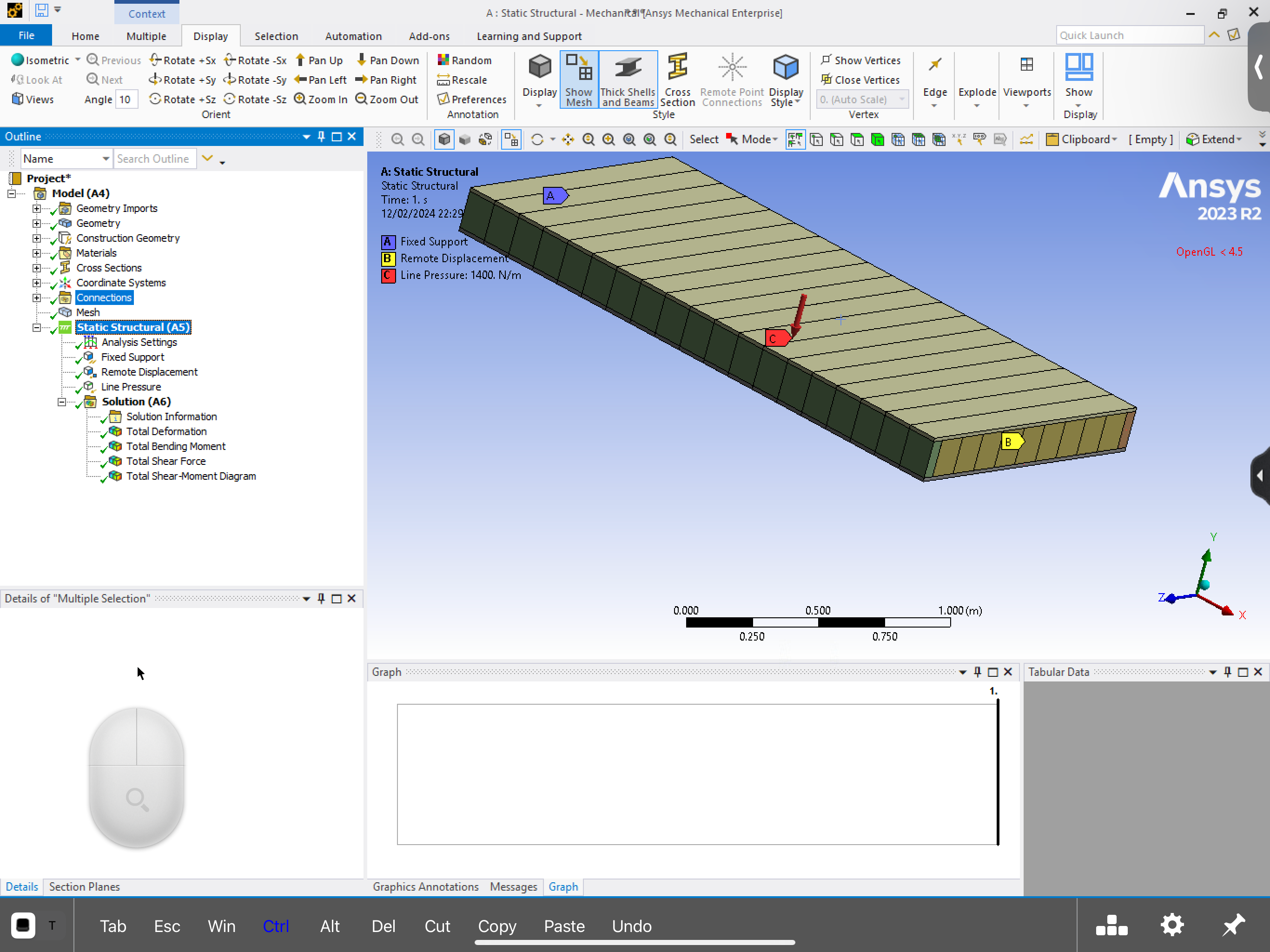
      Bending moment and shear force diagrams have nothing to do with the materials. They only have to do with the loads and supports. If you have a 3D solid block of the correct length, not what you have shown with all the details of the inner foam core and outer shell, but a plain solid block, you can use the Prepare tab in SpaceClaim to extract a Beam model. Bring that into Mechanical and apply the supports and loads then solve. It doesn't matter that the material is Structural Steel.

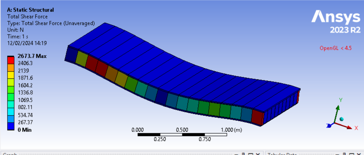
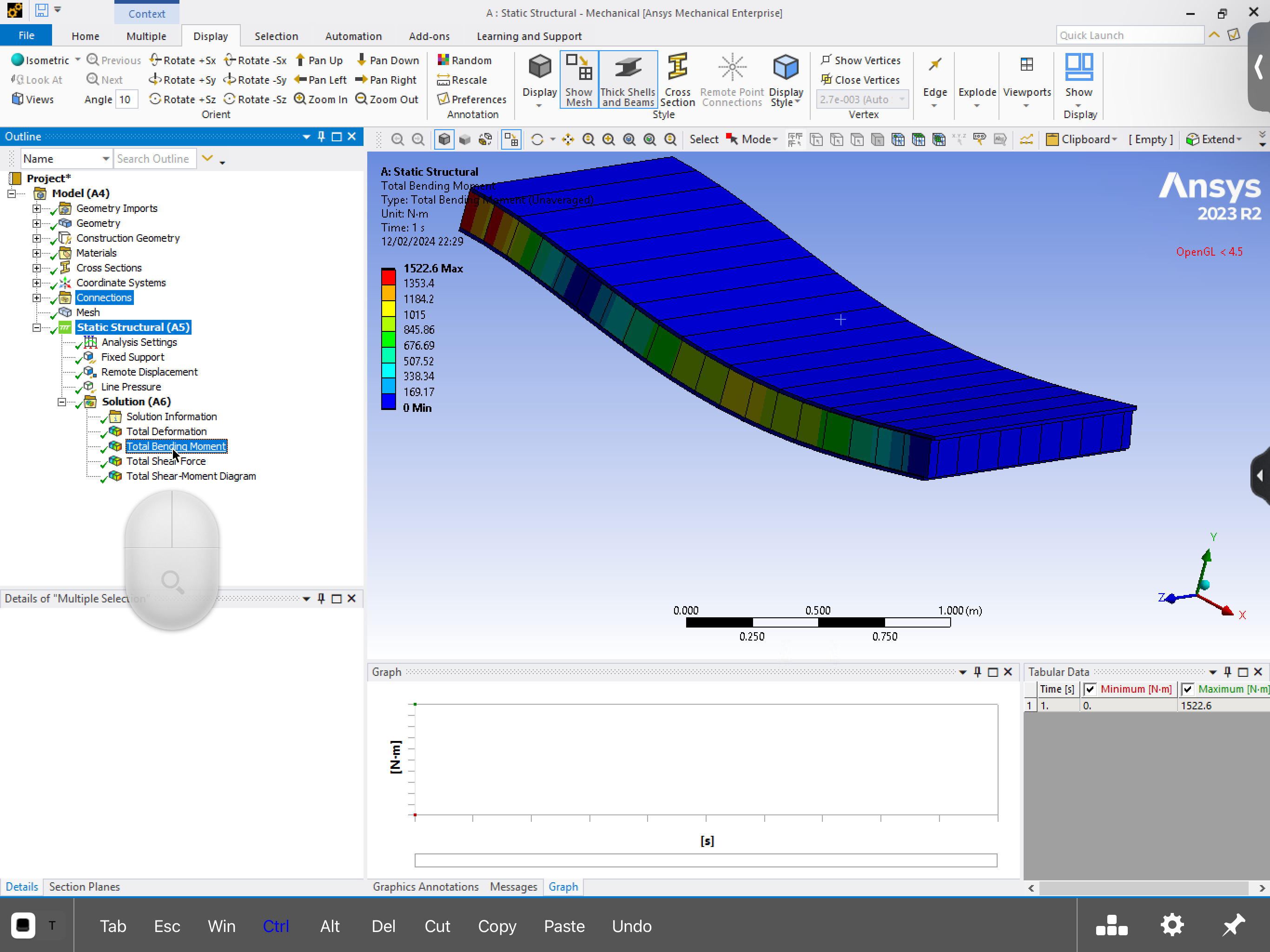
      You need to define Construction Geometry, a Path along the length of the beam.  Then under Beam Results, insert a Shear-Moment Diagram. Set the type to Directional Shear Moment and select the VY display.  Look at this discussion for an example.

    • Farjad Akram
      Subscriber


      I managed to get this. But why is the top face not under any load. After converting everything to beam elements I applied line pressure throughout all the line bodies 


    • peteroznewman
      Subscriber

      I don't understand what you have done. You will need to reply with a detailed description with images to explain it.

    • Farjad Akram
      Subscriber


      I do apologise. Im very new to the software. So as said above I converted the components in the model to beam elements. I used the contact tool to bond the splines which are the side parts to the top and bottom faces. The foam in the middle i bonded to the top and bottom faceboards too. Iv put on my boundary conditions as fixed and used remote displacement for the pin support. I applied the load using line pressure to all the line bodies im assuming this is the correct way. Iv then solved the model for it to give me the bending moment diagram shown. 


    • Farjad Akram
      Subscriber

    • Farjad Akram
      Subscriber

    • peteroznewman
      Subscriber

      You have done much more than what is needed to get that last plot.  All you need is one line along the X-axis that has the fixed support, the remote displacement and the line pressure. You mesh that one line and you get that last diagram.

      You should modify that last diagram and change the type to Directional Shear Moment and select the VY display.

Viewing 7 reply threads
  • The topic ‘Bending moment and shear force diagram’ is closed to new replies.