-
-
February 6, 2024 at 2:17 am
Ryo Agustinus
SubscriberHello, I am doing an analysis on a cold formed steel beam-to-column bolted connection with gusset plate. In this analysis, I need to verify the result granted by ANSYS with the result of the experimental that has been done before. I am doing the analysis using Static Structural in ANSYS Workbench, using properties with young modulus and bilinear isotropic hardening data from the same experimental test. But, after I did the analysis, the result I get doesn't seem to be matching the experimental result. Max P-def of the experimental is 32kN with deformation of 85,83 mm. But I could only get the structure to get nonlinearity behavior over 30 kN, which after I test, I need almost 3 times of the actual load to get the same deformation result. What have I done wrong? Any suggestion? I am using Nonlinear Mechanical Mesh with 15 mm size. If any photo is needed, I would happily attach it in this forum, thankyou very much. Any tips would be appreciated????.
-
February 6, 2024 at 3:01 am
peteroznewman
SubscriberPlease show details of the mesh of the gusset plate and show how the bolts are modeled and if you used a bolt-preload and frictional contact. Please show the analysis settings you used and the step controls. Show the Force-Deflection curve analysis result and the experimental result.
-
February 6, 2024 at 4:01 am
-
February 6, 2024 at 4:08 am
Ryo Agustinus
SubscriberFor the gusset plate I used Nonlinear mechanical, automatic mesh with mesh size of 15 mm. The bolt hole diameter is 12 mm, but I'm not quite sure about this. Because, in the real experiment the bolt diameter is 12 mm, but the hole is 13 mm, I'm afraid that the gap would disturb the analysis, therefore, I make the hole in the gusset 12 mm too, so the contact would be detected. For the bolt modelling, I made the bolt and the nut into one combined geometry. For the bolt I used multizone mesh with Nonlinear Mechanical type and 15 mm in size.
-
-
February 6, 2024 at 4:03 am
-
February 6, 2024 at 4:09 am
-
February 6, 2024 at 4:15 am
Ryo Agustinus
SubscriberÂ
This is the experimental curve I need to verificate my ANSYS result with, the blue wavy curve on the right side is the experimental result curve. The blue curve on the left is the ANSYS result I get when I used the real data into my Engineering Data, the green curve is the ANSYS results I get but with some manipulating in the Engineering Data, I changed the young modulus and also the yield strength of the data to get the green curve, fyi the real data isÂ
Bolt E = 210000 MPa, fy = 758 MPa, fu = 834 MPa
Cold Formed Steel E = 170000 MPa, fy = 474 MPa, fu = 611,39 MPa
Hot Rolled Steel E = 140000 MPa, fy = 321,6 MPa, fu = 465,4 MPa
For all the data I used Bilinear Isotropic Hardening based on the real stress-strain curve obtained from the same experimental. Cold formed steel is used for material of the column and the beam, Hot Rolled Steel is used for the Gusset Plate.
Â
-
-
February 6, 2024 at 4:19 am
-
February 6, 2024 at 4:28 am
Ryo Agustinus
SubscriberThis is the setup of the analysis. I apply fixed support on the bottom of the baseplate, the force on the real experiment is monotonic loading with Isolated Joint test with the force applied 1000 mm from the joint. And the deformation result I need to read is also 1000 mm from the joint, under the beam. My senior suggested to apply 0 displacement on the column so the column doesnt move forward (to the X-axis). For the bolt I'm not using pretension because I dont have the actual data of the force used in the real experiment to lock the bolt. For the contact I used the frictional contact on the beam to column, bolt head to the column and beam profile, gusset plate to the beam and the column. For the contact between the bolt and the bolt hole in the gusset, beam, and the column I used bonded contact.
-
February 6, 2024 at 4:33 am
Ryo Agustinus
SubscriberÂ
If more data is needed, just let me know, I would attach the data. Thankyou for the reply, Peter, really appreciate it.
Â
-
-
February 6, 2024 at 11:31 am
peteroznewman
SubscriberRyo, thank you for a detailed reply.
Changing Young’s modulus to make your model match the experimental Force-Deflection curve is not the correct approach, you should use the true values for the material. I think the discrepancy between your initial model and experiment is due to using a coarse mesh and overly idealizing the geometry and boundary conditions.
The baseplate of the column is likely bolted to the floor. If so, you should fix the bolt holes in the baseplate, not the entire basebplate surface, and use a compression only support to the bottom of the baseplate to allow the baseplate to deform.
You should find out the bolt torque used to tension the bolts in the gusset plate and use a bolt pretension. You should model the actual bolt hole diameter and bolt shank diameter. On the experimental curve, where the slope flattens out around 15 kN, that is probably the gusset plate slipping and the clearance between the holes and the bolts being taken up .When that is finished, the slope goes back to a steeper slope as the bolt shank carries the shear force by contact with the sides of the holes.
How many elements are meshed through the wall thickness of the gusset plate and the beam walls? You need at least 4 linear elements through the thickness and 8 would be better in order for the plastic deformation to be properly represented. The bolt holes need more elements around the circumference, at least 12, and a small element size in the radial direction of each hole surface. You can use a mesh method of Inflation to cause that to happen. Or you can split the body using a cylindrical surface to create an annular ring of material around each hole so that a uniform mesh can be created around each bolt hole. If you split the body, use the Share button on the Workbench tab in SpaceClaim to create Shared Topology on each individual part (beam, gusset plate, column) to connect the mesh without using bonded contact. Don’t use Share on the Assembly otherwise the mesh will connect between the parts and you don’t want that. Using the Inflation mesh method may be safer…
What is the actual conditions at the top of the vertical column? You selected a face and set a displacement, which means that face cannot rotate, but if the true condition is simple contact against a rigid support, then that face should be allowed to rotate. You can do that with a Remote Displacement scoped to that face and then just set X to 0 and leave all others Free. Is it valid to assume the top support is rigid? What is the stiffness of that support? Maybe you should use a spring to ground and enter the spring constant for that support. In that case, you don’t need a Remote Displacement.
What does the column, beam and gusset plate look like at the end of the experiment? Did the parts buckle? Please show a photograph if you can. You can perform an Eigenvalue Buckling analysis on the column to predict the buckled shape, and add a tiny amount of that deformed shape to your Static Structural model to seed the structure with imperfect geometry, which is more realistic than the perfect geometry you have from CAD, before the loads are applied. That will also help the simulation more closely match the experimental result.
-
February 6, 2024 at 2:45 pm
Ryo Agustinus
Subscriber
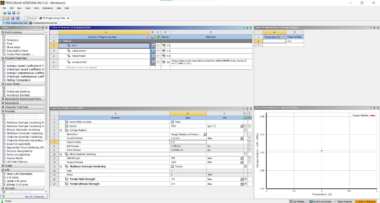
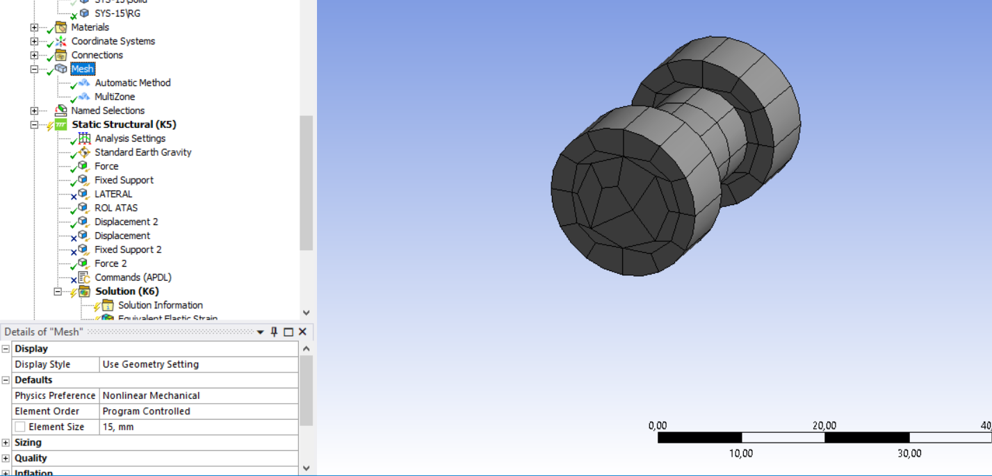
Oh okay, I would use the actual data for the analysis, I gonna revert back to actual data. For the mesh is it okay for me to use 15 mm size, since I tried to use smaller mesh and my laptop doesn't have enough memory to run the analysis.Â
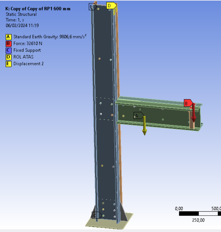
For the baseplate, unfortunately I didn't get much detailed information from my lecturer about the actual setup that has been done, because the experiment was done many years ago. I only managed to get some photo and video documentation that I would attach later on. But, my other lecturer said that it could be bolted onto the floor, so I gonna make some bolt holes in the baseplate. For the connection between the column, haunched on the bottom to the baseplate, my lecturer said that it is welded, can I model that as a bonded contact instead?
For the bolt, so you means that it is okay to model the bolt shank diameter by 12 mm, but the bolt hole in the column, beam, and gusset plate by 13 mm. For the contact is it correct to still apply the contact bodies with the bolt hole and the target bodies with the bolt shank although they doesn't make contact on the beginning of the analysis? For the bolt I just checked my archive, I got the photo of the bolt which I saw that the bolt is also using bolt ring, do I need to model the bolt ring also, and for the nut can I keep the bolt and the nut combined or do I need to split the body?
For the elements on the gusset I used just 1 segment through the thickness, I gonna change the mesh using sweep with 4 elements, is that the correct method to do the linear mesh? For the mesh method on the bolt holes you recommended, I haven't tried it yet, but I gonna do it later. Thankyou for the suggestion.
For the actual condition on the top of the column, I am not quite sure but on the picture I saw before, I could see that they are using some kind of lateral restraint on the Isolated Joint Test setup, I gonna give the picture as an attachment. But based on the condition, I could assume that it's just a frame used to hold the column so it doesnt move along with the beam.Â
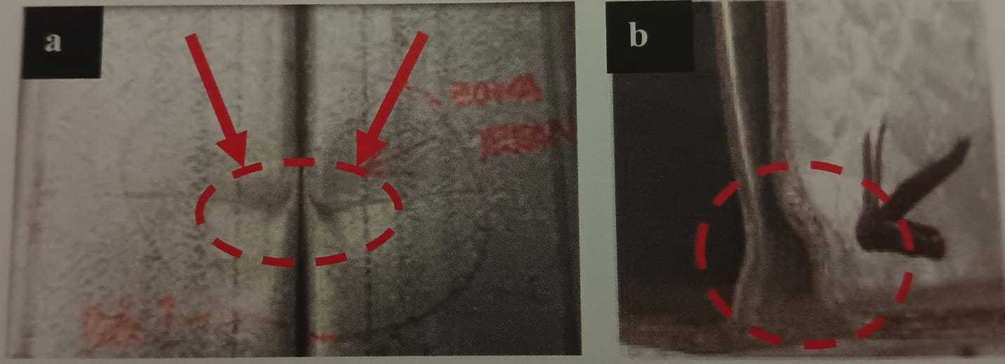
For the specimen condition after the experiment, the column does buckle a bit on the joint, the experimental test actually done 9 kinds of test, 3 beam to column with rectangular gusset plate, 3 with rectangular gusset plate with flange cleat, 3 with haunched gusset plate. I need to verify the rectangular and the haunched one, on the other experimental result I saw on the report, I could see also that some beam managed to penetrate the column a bit, leaving a dent on the column profile. For the eigenvalue buckling analysis you suggested, is it just the column I need to do analyze or the other part also like the baseplate, the bolt, the beam, the gusset plate?
For the photograph of the experimental, I would attach some on the upcoming reply
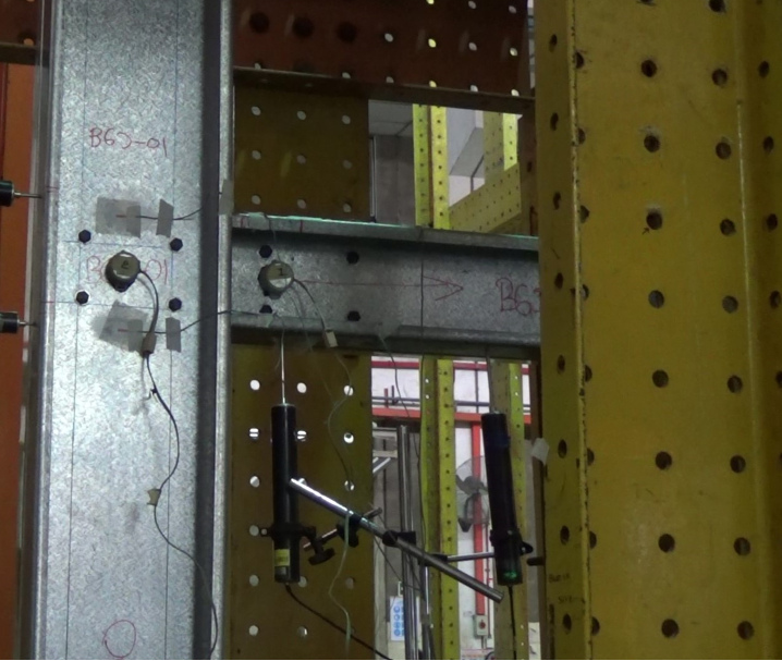
This is the condition before testing
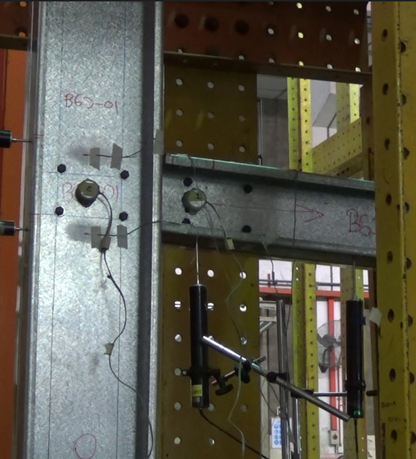
This is the condition after testing
This is the condition of the column and the beam
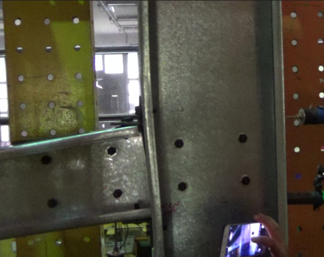
And this is the illustration of the IJT setup
-
-
- The topic ‘Solution seems to be different from the experimental results’ is closed to new replies.
- At least one body has been found to have only 1 element in at least 2 directions
- Script Error Code:800a000d
- Element has excessive thickness change, distortion, is turning inside out
- Elastic limit load, Elastic-plastic limit load
- Image to file in Mechanical is bugged and does not show text
- Help to do quasistatic analysis in static structural module
-
1932
-
839
-
599
-
591
-
366
© 2025 Copyright ANSYS, Inc. All rights reserved.