Ansys Assistant will be unavailable on the Learning Forum starting January 30. An upgraded version is coming soon. We apologize for any inconvenience and appreciate your patience. Stay tuned for updates.
Electronics

Electronics

Topics related to HFSS, Maxwell, SIwave, Icepak, Electronics Enterprise and more.

Not showing correct current density for case II:

    • Vedant Sane
      Subscriber

      Hello,

      Currently, I am facing an issue with the current density plot for my 3D simulation model. Description of the problem is as follows:

      Case I:

      Simulation of single slot geometry is carried out with the boundary conditions as shown in following figure:
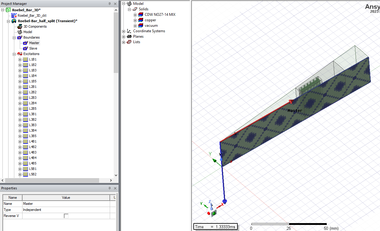
      Where, opposite face is with Hdep = -Hind
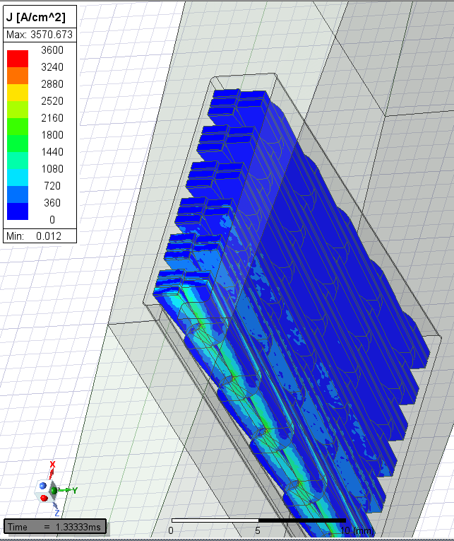
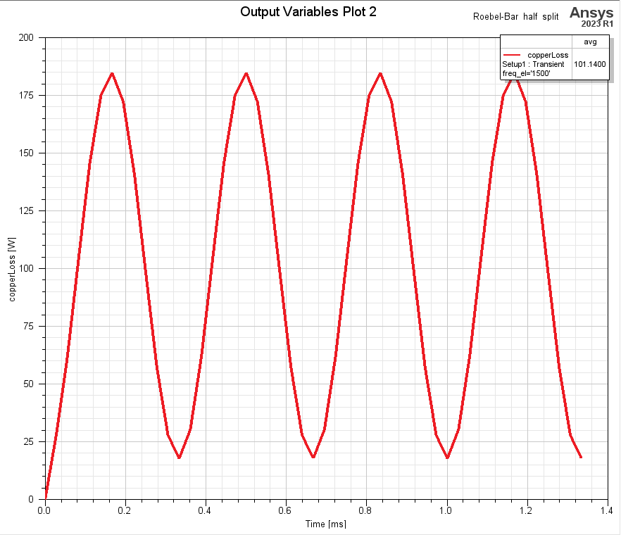
      following figures shows current density plot at 1.3 ms at 1500Hz frequency and SolidLoss respectively (avg = 101.14 W)
      Case II:

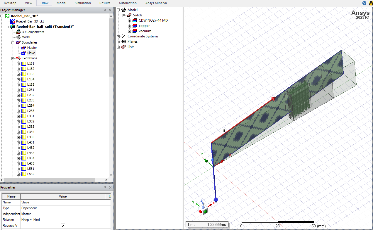
      However to reduce the size and simulation time of the model symmetric boundary conditions are used as follows:
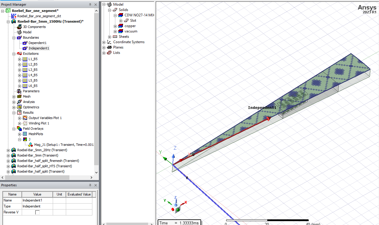
      Where, opposite face is with Hdep = Hind
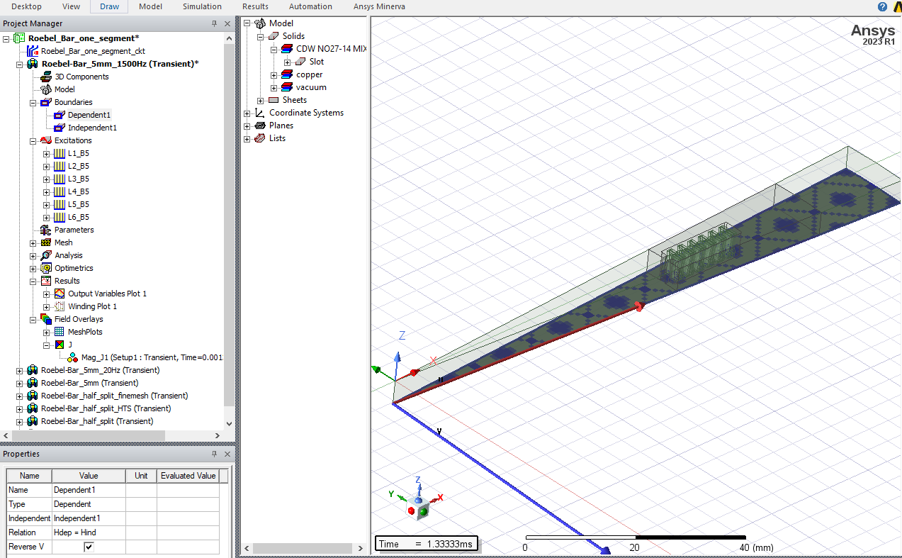
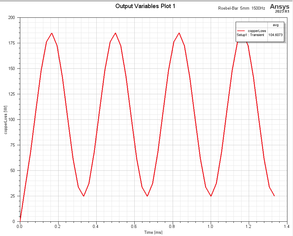
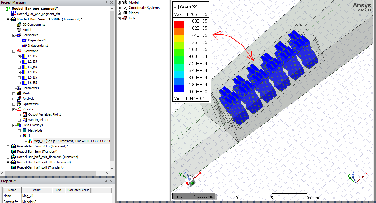
      with these boundary conditions and at same operating point SolidLoss was found to be same with the use of proper multiplication factor since the active length of the geometry is reduced. (104.61 W). However, when it comes to current density plot it does not match with case I
    • DELI
      Ansys Employee
      hi, those two cases are representing different geometries, results will not be the same. You can do a visual check by plotting current density with "full model" box checked, when create the field overlay plot.
    • Vedant Sane
      Subscriber

      Hello,

      thanks for your reply. inspite of different geometries, final result should be the same. because, it is dependent on boundary conditions and symmetry multiplier. As you can the the losses are almost same but the current density in second case does not seem to match with the first case.

Viewing 2 reply threads
  • The topic ‘Not showing correct current density for case II:’ is closed to new replies.
[bingo_chatbox]








