General Mechanical

General Mechanical

Topics related to Mechanical Enterprise, Motion, Additive Print and more.

curved plate simulation

    • amir_ms81
      Subscriber

      Hello everyone,


      I should simulate a curved plate with Ansys structural. for the flat plate, the result seems to be good but for the curved plate, the results are not correct. I compared the result with my experimental results and it shows that the deflection in experiments is 1000 times higher than the Ansys results.


      if anyone has experience with this, it would be grateful to help me.


      thanks


      geometry

    • Sandeep Medikonda
      Ansys Employee

      Hi Amir,


        Can you provide some details on how you are setting up the model? It will help if there are snapshots of your model and also on how the experiments are done.


      Regards,


      Sandeep

    • amir_ms81
      Subscriber

      Thank you, Sandeep


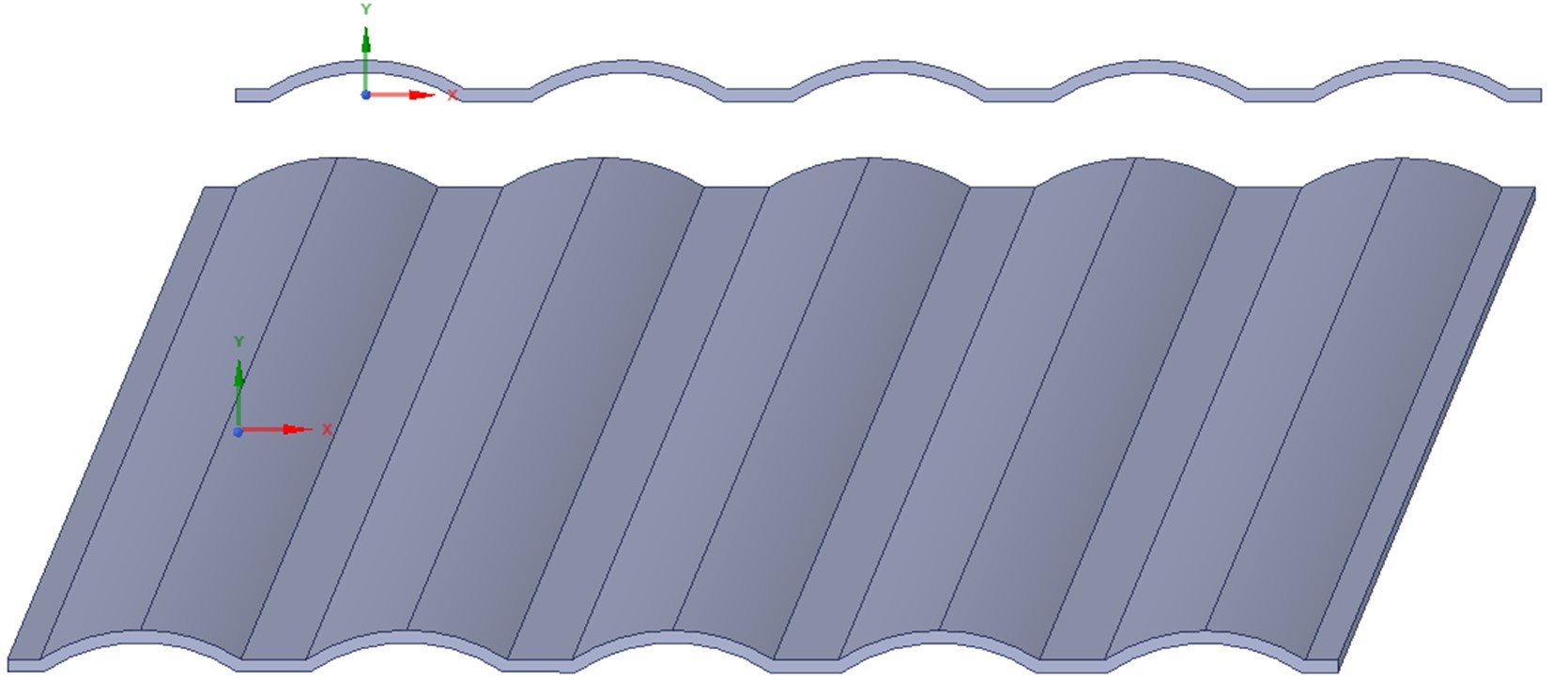
      in the figure below, you can find my boundary condition that I used and also I used fine grids. the device, we use for the measurement is very simple. it includes two surfaces which we apply forces and we can measure the clearance between them. I know that this shows the average deformation but my numerical results are really far from the experiments.


      Also, I used different boundary condition and configuration, I used displacement instead of force also, I tried to simulate exactly the same as the experimental setup but the results were in the same order. even I tried to change the type of element to Slosh or structure 181,187 and ... but the results were the same. in addition, I simulated this geometry as a shield but the result did not change.


      in my experiment, by applying 100N we have 1e-2 mm deformation, but the numerical simulation shows that it is 1e-6 !!!!


    • Sandeep Medikonda
      Ansys Employee

      Amir, 


      Can you double check if you are using the correct units? I sometimes forget to check that.


      Regards,


      Sandeep

    • amir_ms81
      Subscriber

      yes, for the 100N, we measured 12 microns. and the pic below is my simulation. the maximum deflection is 4.9e-5 mm or 4.9e-2 micron. I am really confused because it is a very simple case. I do not know what is happening.


    • peteroznewman
      Subscriber

      Hello Amir,


      I can look at your model if you Attach a Workbench Project Archive .wbpz file to the post above.


      Regards,


      Peter

    • Sandeep Medikonda
      Ansys Employee

      Also amir,


        I still couldn't quite understand how you are calculating the deformation experimentally. 


        Is there a chance that you might be comparing deformation vs displacement? Note that there is a difference?


        If so, note that you can insert displacements from the worksheet as shown.


      Please see if this helps? If not can you post images of how your FEA model is setup etc (just click on Static Structural and this will give a nice summary of your complete loading)? Also, are you turning on Large-deflection in your analysis settings (post a picture of the details as well), if not can you try turning that on? Because it looks like there could be some stress-stiffening effects in your model.


      Regards,


      Sandeep

    • Bhargava Sista
      Ansys Employee

      Amir,


      You may want to do an Eigenvalue buckling analysis to see what is the load at which the plate buckles. In your experiment, does the plate buckle? If the load applied is close to the buckling load, then you may not be applying sufficient load yet, once the structure buckles the displacement increases rapidly. The Eigenvalue buckling analysis does not take much time to run so it is worth running it before doing further debugging

    • amir_ms81
      Subscriber

      peter,


      Thanks, bellow you can find my case.


      https://www.dropbox.com/s/ordovll7si8x30k/CURVED_PLATE.wbpz?dl=0


    • amir_ms81
      Subscriber

      Sandeep,


      the results were calculated when Large deflection was. Also, I checked that it is the same. I am really wondering why it is happening. at least the order of results should be the same but the difference is too much. the link below is my case file. if you have time, I would be grateful to look at it.


      https://www.dropbox.com/s/ordovll7si8x30k/CURVED_PLATE.wbpz?dl=0

    • amir_ms81
      Subscriber

      bsista,


      I know what you are talking about but my case is not buckling. it is just a simple deformation. but if you think the buckling may happen, I would be grateful if you check it for me. for the experiments, we can't see the surfaces thus we don't know if buckling is happening or not.

    • peteroznewman
      Subscriber

      Amir,


      I have opened your model (which ANSYS employees are not allowed to do), and see the problem.


      The mesh is far too coarse to give you a good result.


      Below is the kind of mesh you want.


      A close up shows there are 3 elements through the thickness of the part. This is barely enough.


      You would be better off converting this into a shell model that will be much more capable of representing the bending of the part.


      I will have more to say on a later post.


      Regards,


      Peter

    • peteroznewman
      Subscriber

      Amir,


      Another idea is to create a 2D Plane Strain model, since the part is so long.


      I expect the part is being pressed between two plates. That is what I have done in this model.


      You can attach Workbench project archives to your post after you post it, as I have done for this model.


      Regards,


      Peter

Viewing 12 reply threads
  • The topic ‘curved plate simulation’ is closed to new replies.