-
-
June 14, 2023 at 11:52 am
Mustafa Babagiray
SubscriberHey everyone,
I am working on turbine blade optimization for a specific flow rate. I have the CAD design of the turbine runner attached below(1), but I wanted to convert it into the bladegen by using the data import wizard. I attached the steps that I have taken in the data import wizard, I selected hub and shroud curves and the meridional profile is created. (No problem until here). However, as you see in picture 7, I want to have the hub surface as a flat surface as depicted in the picture's red lines without any changes in the blade shape. I mean everything is correct except the flow path starting point. It should be perpendicular to the blades. Do you have any suggestions on how to do it?

     (1)
2
3
4
5
6(bladegen view)
7
-
June 16, 2023 at 3:26 pm
C N
Ansys EmployeeHello Mustafa,
I recommend you  to set the zr locations for the hub & shroud curves at outlet and TE to be the same values. You can double click on the points and set the values. This should create a flow path perpendicular to the blades . I am attaching the user guide on link on flow path feature for further details.
10.2.1. Flow Path Contour Creation (ansys.com)
10.2.2. FlowPath Feature (ansys.com)
I hope this helps you solve the problem.
Thanks,
Chaitanya Natraj
-
- The topic ‘
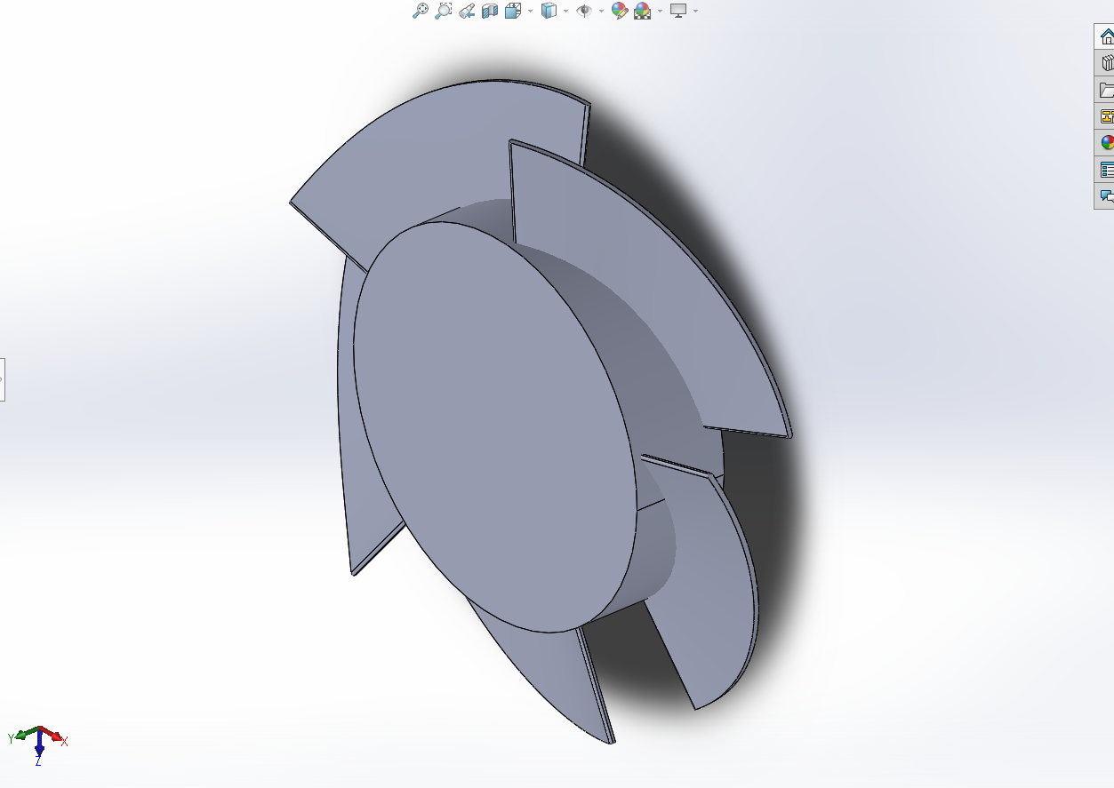
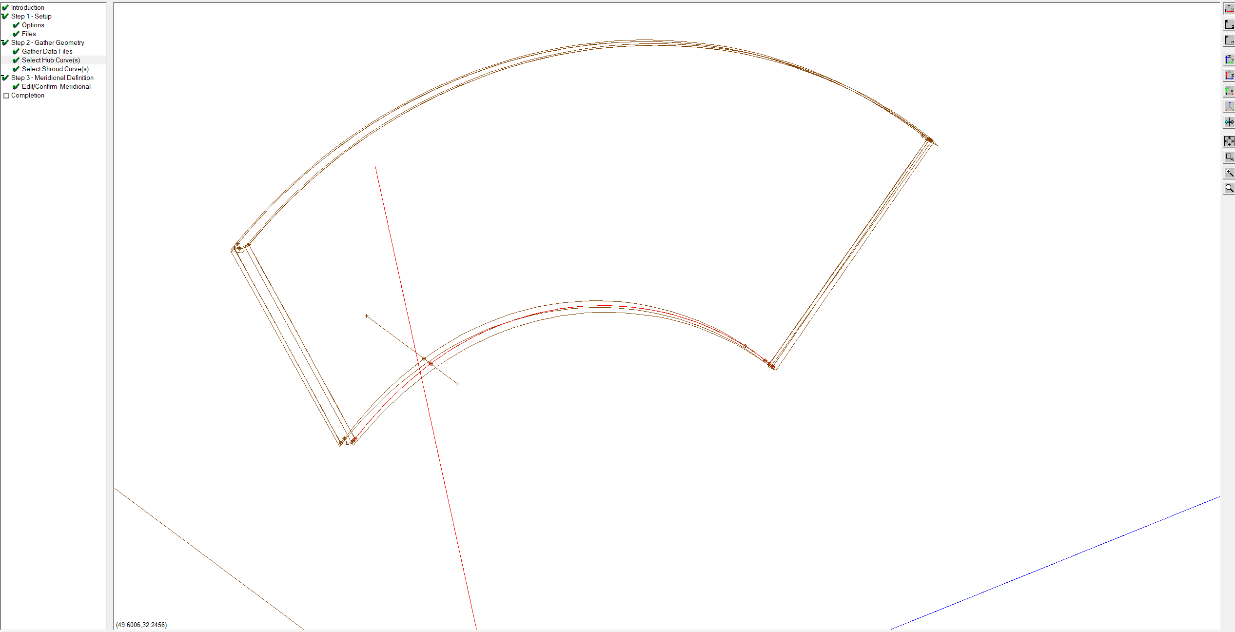
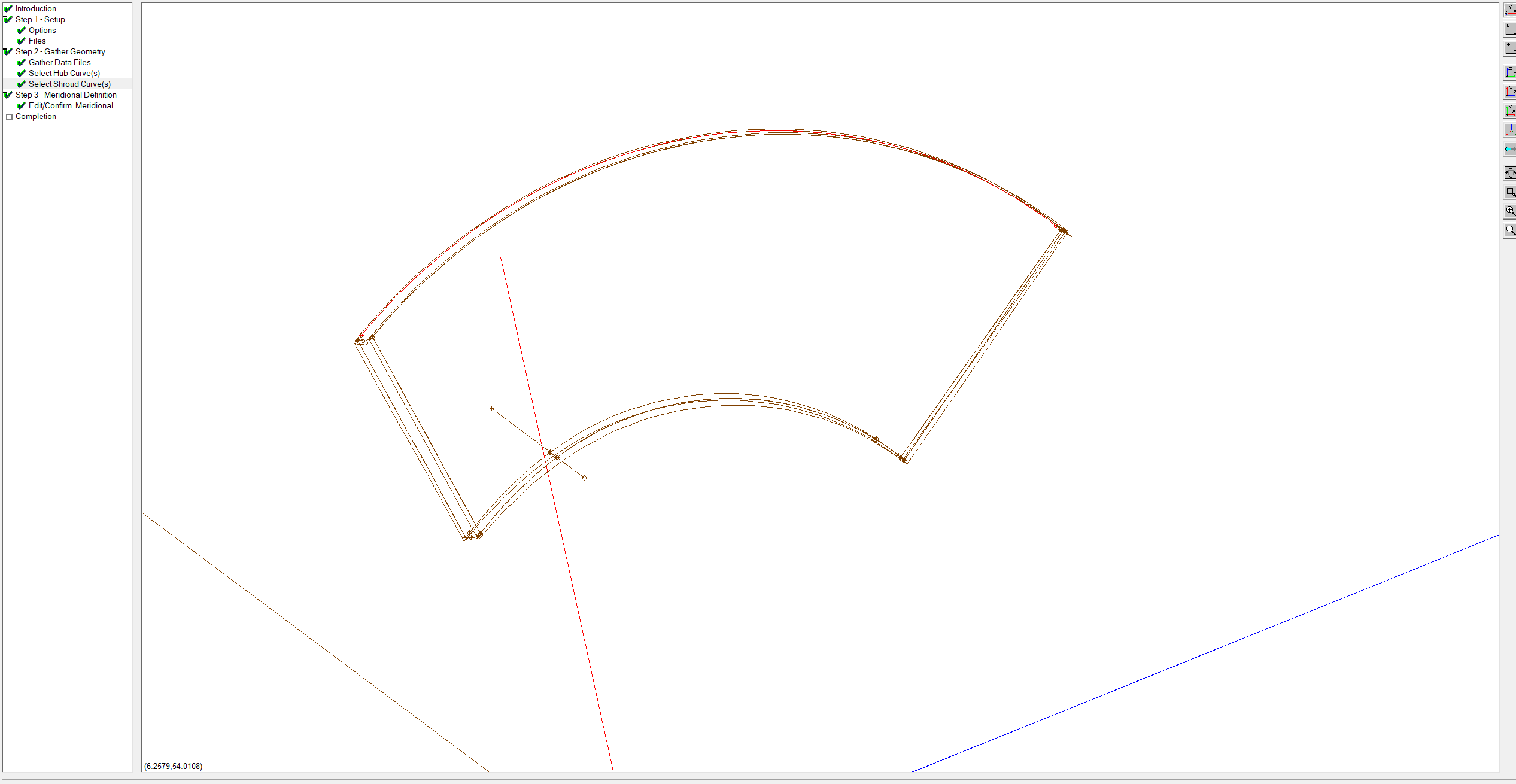
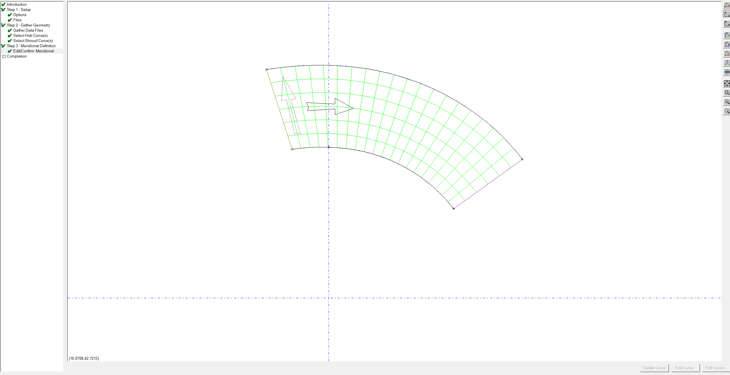
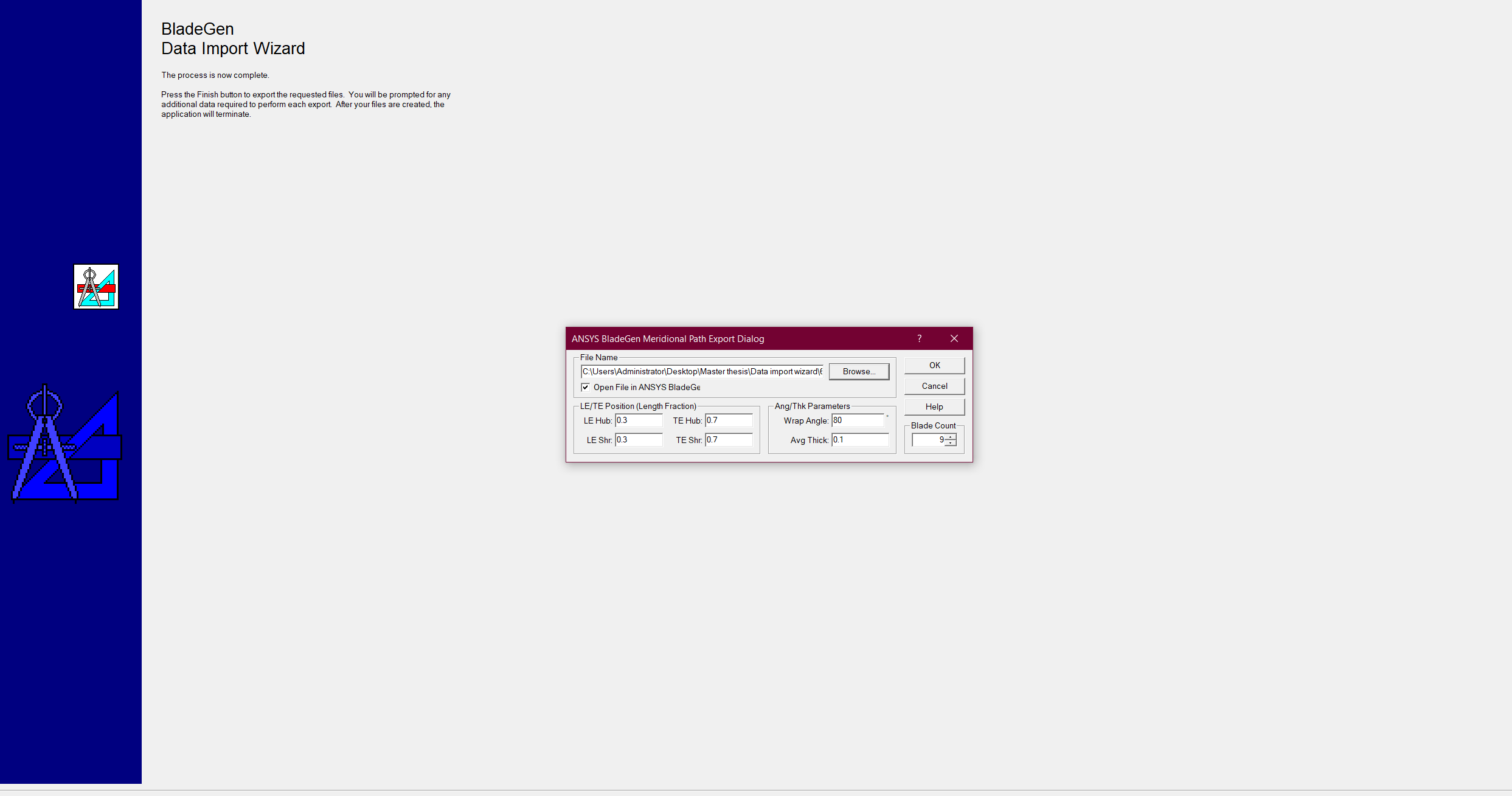
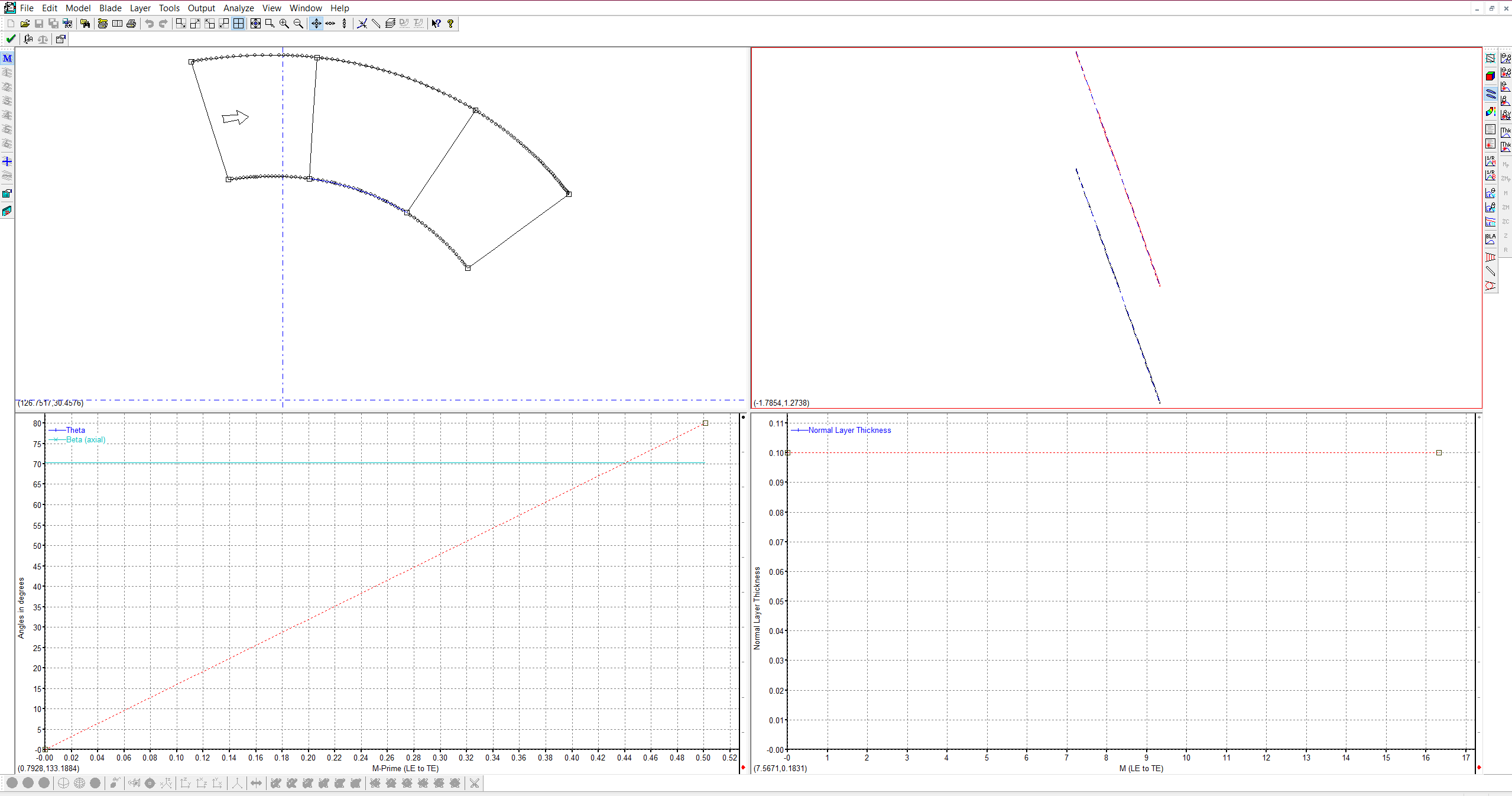
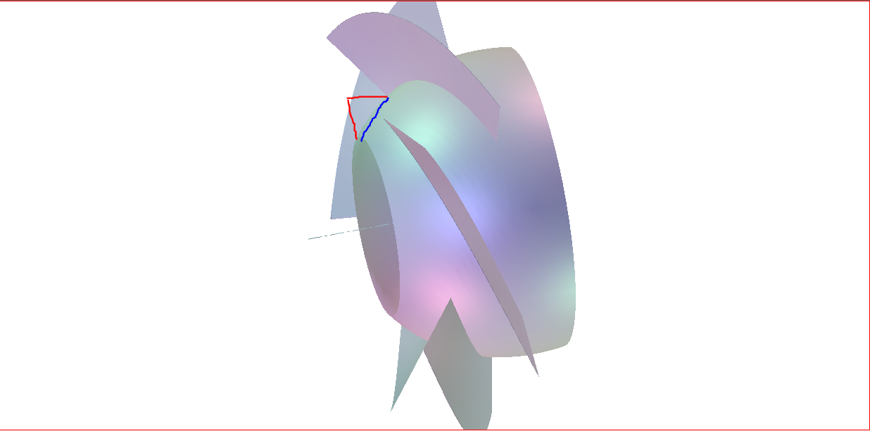
Bladegen Data import wizard (Creation the existing turbine blades in bladegen)’ is closed to new replies.
-
4919
-
1608
-
1386
-
1242
-
1021
© 2026 Copyright ANSYS, Inc. All rights reserved.


