TAGGED: hfss, periodic, plane-wave
-
-
March 3, 2023 at 10:32 am
csernyava.oliver
SubscriberHi All!
I'd like to ask about a confusion of mine regarding periodic structures in HFSS.
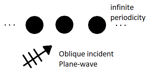
I'd like to model a linearly periodic sphere structure (infinite periodicity) with an oblique incident Plane-wave.
As far as I understand, I need the 'Coupled' boundary condition (Primary, Secondary) for the faces of the periodic dimension. Otherwise, I can use PML on the remaining faces. Then the excitation can be a Plane-wave set for the specific incidence.
The parameter that is not clear is the 'Scanning angle' or, as I understand, the phase difference between the two Coupled boundary surfaces. I would understand this Scanning angle as a virtual incident Plane wave from that direction, helping to imagine the phase compensation on the boundaries. However, assuming this theoretical model for the Scanning angle, I don't get the correct results for the solution.
I would like to ask if the described way to model an infinite periodic structure, with an oblique incident plane wave is correct, or if there is another way. Also, what is the meaning and significance of the Scan angle property of the Coupled boundary condition?
Thank you for all the comments in advance!
-
March 27, 2023 at 12:20 pm
Praneeth
Forum ModeratorHi Oliver,
Thank you for reaching out and your patience is much appreciated.
The scan angles for a coupled or lattice pair can be used to calculate the phase delay between the electric field at the primary boundary to the secondary boundary. Please go through this link - Ansys Electronics 2023 R1 - Assigning Boundaries in HFSS for detailed information on the same.
Best regards,
Praneeth.
-
- The topic ‘Infinite periodic structure HFSS’ is closed to new replies.


- HFSS Incident Plane Wave excitement mode
- Simulation of capacitor combining eddy currents with displacement currents
- How to calculate eddy and hysteresis losses of the core?
- Ansys Maxwell 3D – eddy current
- How to determine initial position in motion setup
- dq graph non-conformity
- Simplorer+Maxwell Cosimulation results and Maxwell results mismatch
- Parametrizing coil “terminals” with coil geometry
- On-chip inductor design
- Maxwell circuit – PWM

-
1572
-
602
-
599
-
591
-
366

© 2025 Copyright ANSYS, Inc. All rights reserved.


