-
-
September 9, 2022 at 11:53 am
-
September 21, 2022 at 8:46 am
NKC
Forum ModeratorHi junaed.buet,
For Maxwell 2D transient designs with cylindrical rotational motion setup, the transient solver can
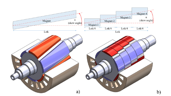
take into account the effects of skewed rotor slots by using a multi-slice model.Continuous skew, the default, is used for induction motor rotors.
Step skew is used for permanent magnet rotors.
The left image(a) in your picture can be represented practically as a sliced model.
You can refer to the “Model Settings Tab > set skew model options” sections under maxwell help.
Regards,
Navya
-
September 21, 2022 at 8:41 pm
GLUO
Ansys EmployeeHello @junaed.buet,
The main difference between continuous and step option is the way of defining the skew angle. When you choose continuous as skew type, the calculation is still discrete. You could choose a larger number (5~11) for slice number to make it closer to the continuous PM in practice.
Regards,
GLUO
-
- The topic ‘Rotor Skewing’ is closed to new replies.


-
3767
-
1333
-
1173
-
1090
-
1014

© 2025 Copyright ANSYS, Inc. All rights reserved.


