TAGGED: airgap, force, force-calculation, force-density, magnetic-transient
-
-
December 24, 2021 at 9:49 am
thetai158
SubscriberHi everyone,
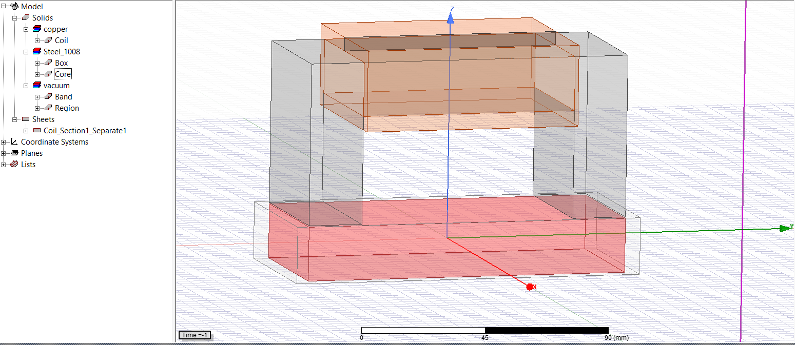
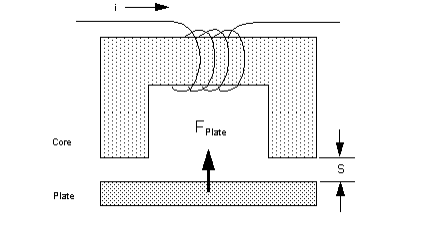
I am simulating an U-magnet and am having problems with the way the magnetic force is calculated in the model.
My model has: N=400 (turn), I=0,3(A), g=0,5(mm), A=0,0022 (m2) and m=1.04kg.
December 25, 2021 at 5:35 amSubscriberCan you re-comment? Thanks!
December 29, 2021 at 4:20 pmDELI
Ansys Employeewe will need more information to answer your question. Which solver are you using? which force parameter are you assigning? and which object are you assigning the force parameter on?
December 29, 2021 at 4:24 pmSubscriberI'm using Transient Solution type and force parameter is virtual force. I assign the force parameter for the box under the magnet.
December 30, 2021 at 1:28 amR_Caicedo
SubscriberSome tips with simulation problems involving airgaps and steel cores.
-verify that the relative permeability of the core is large enough to made the reluctance of the core negible. In fact, you are calculating the force of the magnet with the derivative of the magnetic energy with the assumption that the reluctance of the air gap is much bigger than the reluctanc of the core.
-You have two airgaps each of then with 0.5 mm of lenght in each leg of the magnet OR you have 2 airgaps with 0.25 mm lenght in each leg of the magnet? Sometimes the students miss the fact that there are two airgaps in this type of problem. If g represent the total airgap (both legs) then the force must be arroun 39.81 [N], but if g represent the airgap of each lenght, the force will be arround 9.95 [N].
-Another problem that will appear is that there are some fringe flux in the airgap. The equation that you are using assume that there is no fringe flux. A little fringe flux can modify the value of the force but not mucho more because you airgap is little.
-You can use the magnetostatic solver for this problem.
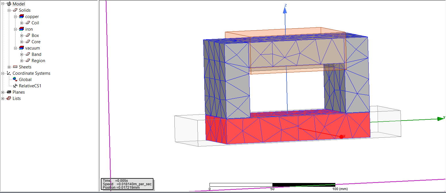
-Can you show us the mesh for this problem.
Can you put all the dimensions used in the problem and the force calculatd by maxwell?
December 30, 2021 at 2:05 amSubscriberI used iron instead of steel_1008 with relative permeability is 4000 but the my calculation result still different from ansys.
I have 2 airgaps each of then with 0.5 mm of lenght in each leg. My calculation result is arround 39.81 [N] but ansys result is arround 20.6 [N].
I tried to use McLyman formula to calculate the effect of fringing flux (FF) but the result still so much different.
I want to use Transient solution to link with Matlab/Simulink and control the box position by controller in Simulink.
December 30, 2021 at 4:57 pmSubscriberHi again
The problem seems to be the reluctance of the core. My suspect is that the reluctance of the core can't be neglected.
You would try to calculate again the force of the magnet but without neglecting the reluctance of the core.
December 30, 2021 at 5:41 pmSubscriberHi
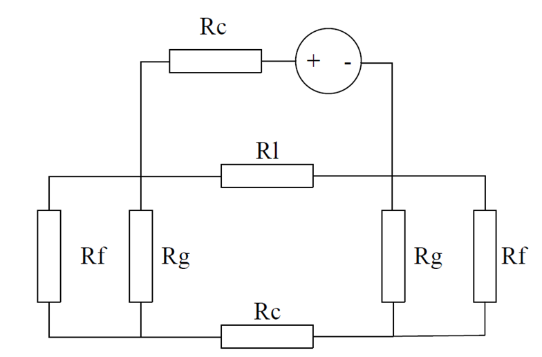
I used to use reluctance network to calculate inductance L=N*N/Rtotal ( neglect Rf: fringing effect, Rl: leakage flux)
Rtot=2Rc+2Rg, Rc=lc/(2*╬╝0*╬╝r*A); Rg=g/(╬╝0*A) -> L=(N*N*╬╝0*A)/(lc/╬╝r+2*g) -> F=(N*N*╬╝0*A*I*I)/((lc/╬╝r+2*g)*(lc/╬╝r+2*g))
With magnetostatic solver i can defind lc/ur=1,81/4000 but with transient solver lc/ur isn't constant.
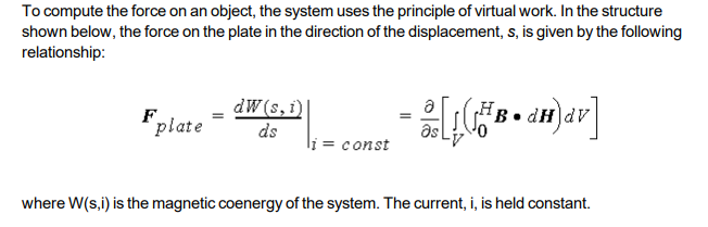
January 11, 2022 at 9:53 pmAnsys EmployeeMaxwell transient is calculating virtual force, you can search " virtual force" in manual to find the equation that the solver is using.
 Note, when assigning virtual force parameter on selected object, user needs make sure the object is not touching any other object with a good distance air gap in between.
October 24, 2023 at 9:34 pmSadegh Esmaeilirad
SubscriberHi
I'm encountering a situation similar to what you described. I designed an inductance, and I've noticed discrepancies between my calculated parameters and those obtained from Maxwell's calculations. Specifically, when there's a significant air gap, approximately exceeding 1mm, it appears that the fringing flux effect becomes noteworthy and should be factored into the calculations.
However, it seems that Maxwell doesn't inherently account for the fringing flux effect. I'm curious to know whether Maxwell includes this effect in its calculations. If it does, I'd like to understand how to modify or view the formula that incorporates the fringing flux effect to confirm its consideration.
Thanks a lot
Viewing 9 reply threads- The topic ‘How is the magnetic force in ansys maxwell calculated?’ is closed to new replies.
Innovation Space Trending discussions
 Top Contributors
-
peteroznewman
 6455
6455 -
scabo
 1906
1906 -
Dennis Chen
 1457
1457 -
javat33489
 1308
1308 -
Shyam Prasad V Atri
1022
Top Rated Tags
© 2026 Copyright ANSYS, Inc. All rights reserved.
Ansys does not support the usage of unauthorized Ansys software. Please visit www.ansys.com to obtain an official distribution.
-