-
-
November 17, 2021 at 5:48 pm
pramod1314
SubscriberHello Everyone
I have got a stress singularity issue at a sharp corner. If I refine the mesh stress increases and doesn't converge.
I added a small fillet at the corner; however that did not help.
I would really appreciate if someone can tell how to deal with these kind of problem?
Thank you in advance.
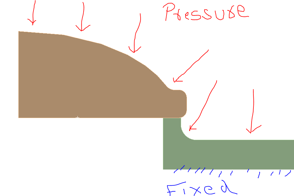
This 2D-axisymmetric model. Pressure applied from top, bottom fixed, Frictional contact(0.15).
November 17, 2021 at 6:12 pmpeteroznewman
SubscriberYou got rid of the singularity when you changed the sharp corner to a radiused corner.
Now you have Hertzian Contact Stress, which is not a singularity. I don't believe the stresses will keep increasing without limit as the element size gets smaller and smaller. I believe you will be able to plot a mesh convergence plot showing a converging trend line.
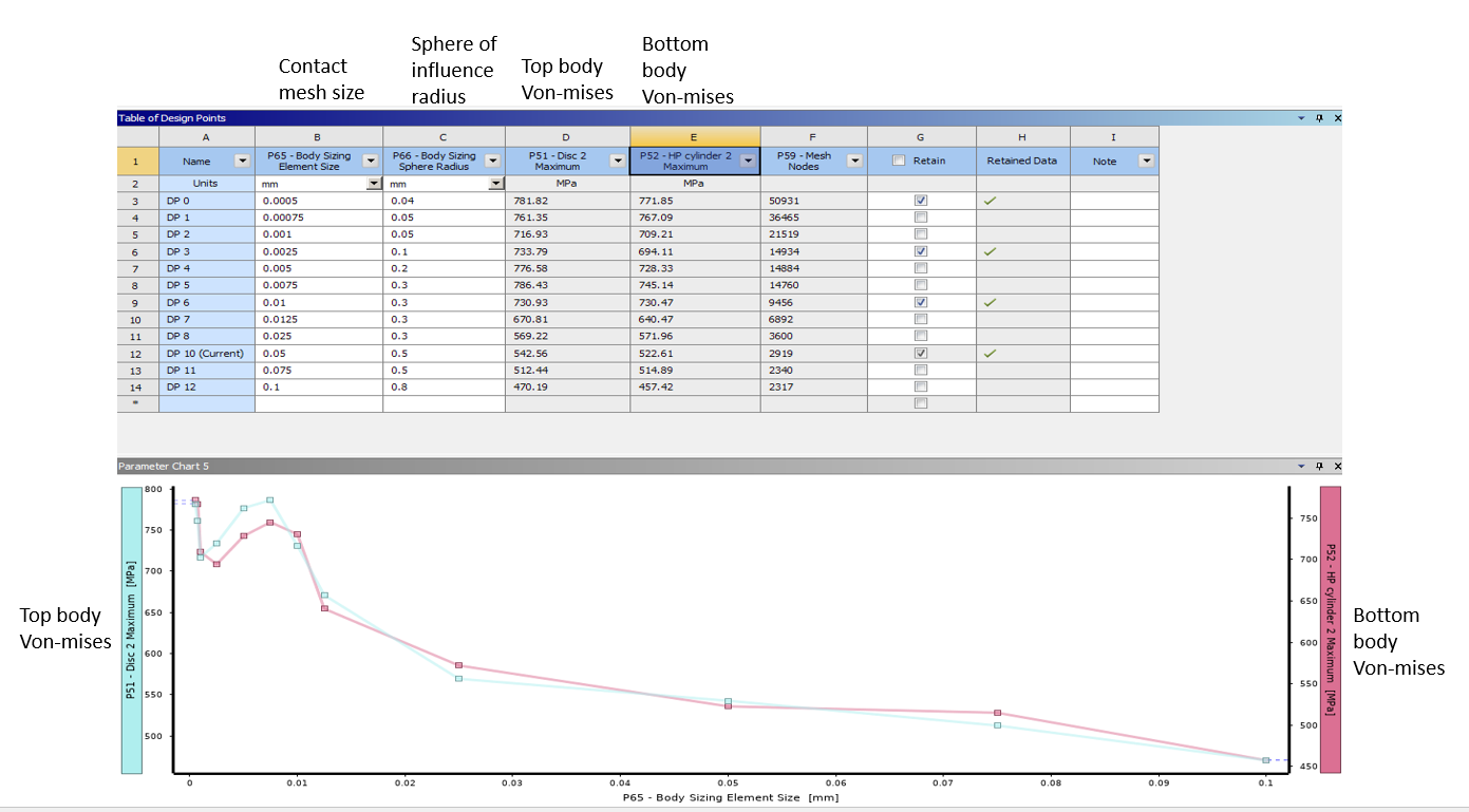
Please reply with a table of stress versus element size for the model with the radiused corner.
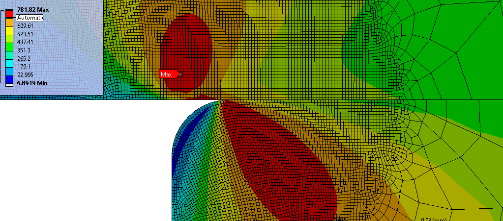
Also, you only need small elements over a small region near the contact point. Sizing with the Sphere of Influence is a good way to get that effect, but you have to create a Coordinate System at the contact point first.
November 17, 2021 at 6:58 pmNovember 17, 2021 at 9:32 pmpeteroznewman
SubscriberDo not change the Radius of the Sphere of Influence. Make the radius at least 2X larger than the distance from the contact point to the location of maximum stress, much like what you show above.
Best practice is to set the element sizes at a constant ratio. For example using a ratio of 2, you can run the following sequence:
.0005
.001
.002
.004
.008
.016
.032
What is the global element size away from the refined mesh? An image of that would be good to see.
Is the plot True Scale? Look at the penetration the contact delivers, it looks excessive. You might reduce some of the noise in the stress by reducing the Displacement tolerance in the Analysis Settings from the default 0.5% to 0.01% and and reduce the Penetration tolerance on the Contact.
What order is the mesh? Change the element order to Linear and run that sequence. Linear elements will also reduce the solution time.
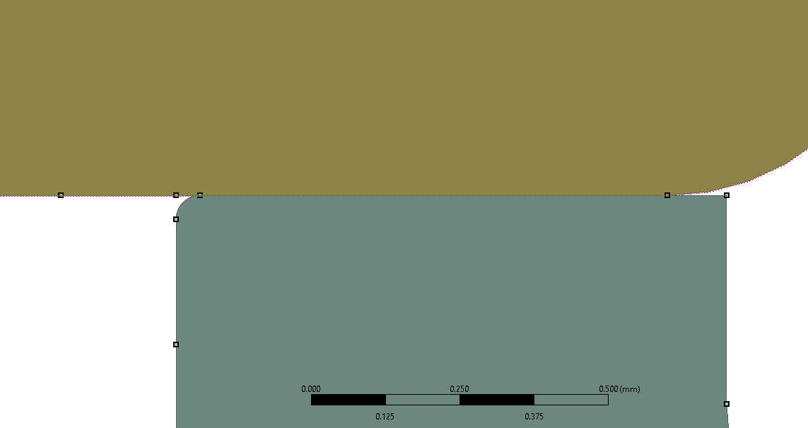
´╗┐If you leave the ruler in your screen grab, that would help to understand the scale of the geometry. What is the blend radius on the corner?
How much precision do you need in the stress result? Is 10% adequate? Why do you need more precision than that?
There is definitely no singularity because for a typical singularity, the stress almost doubles when the element size is cut in half.
November 22, 2021 at 5:13 pmpramod1314
Subscriber
Thank you for informative insight about stress increase in singularity. Sorry for late reply, It took me some time to do different iterations.
Details:
Order: Linear
Radius of vertex blend: 0.01 mm
Mesh size top surface 1mm, bottom surface 2mm, contact surface other than the corner 0.25 mm, contact at the corner mesh size is varied using parametric study.
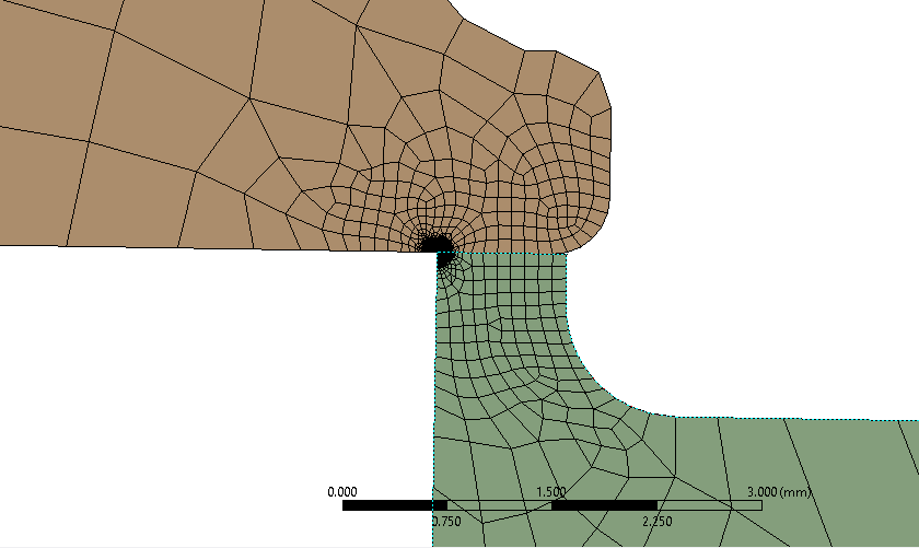
Plot is in true scale in the results now.
I have found the penetration in my model. As you suggested i used penetration tolerance option to decrease the penetration but if I go for lower tolerance the stress values increases so I am not sure how much should be the acceptable penetration tolerance or is there any way to find it out? (I used tolerance (as you mentioned in one of your posts) such that penetration is 10^-6 but the stress values were pretty high)
or I can use Normal Lagrange method to avoid this penetration issue? But using Normal Lagrange gives me very high stress.
Result:
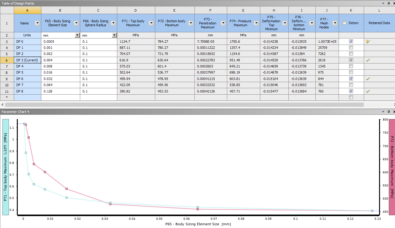
1) Augmented Lagrange, penetration tolerance: Program controlled
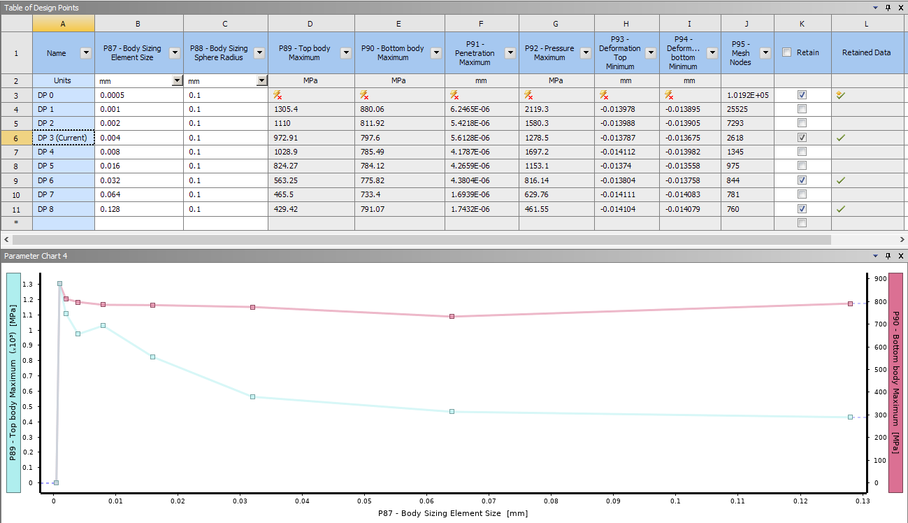
 2) Augmented Lagrange, penetration tolerance: 0.0001 mm
For mesh size 0.004 mm at the corner results would look like this:
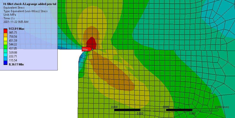
3) Normal Lagrange
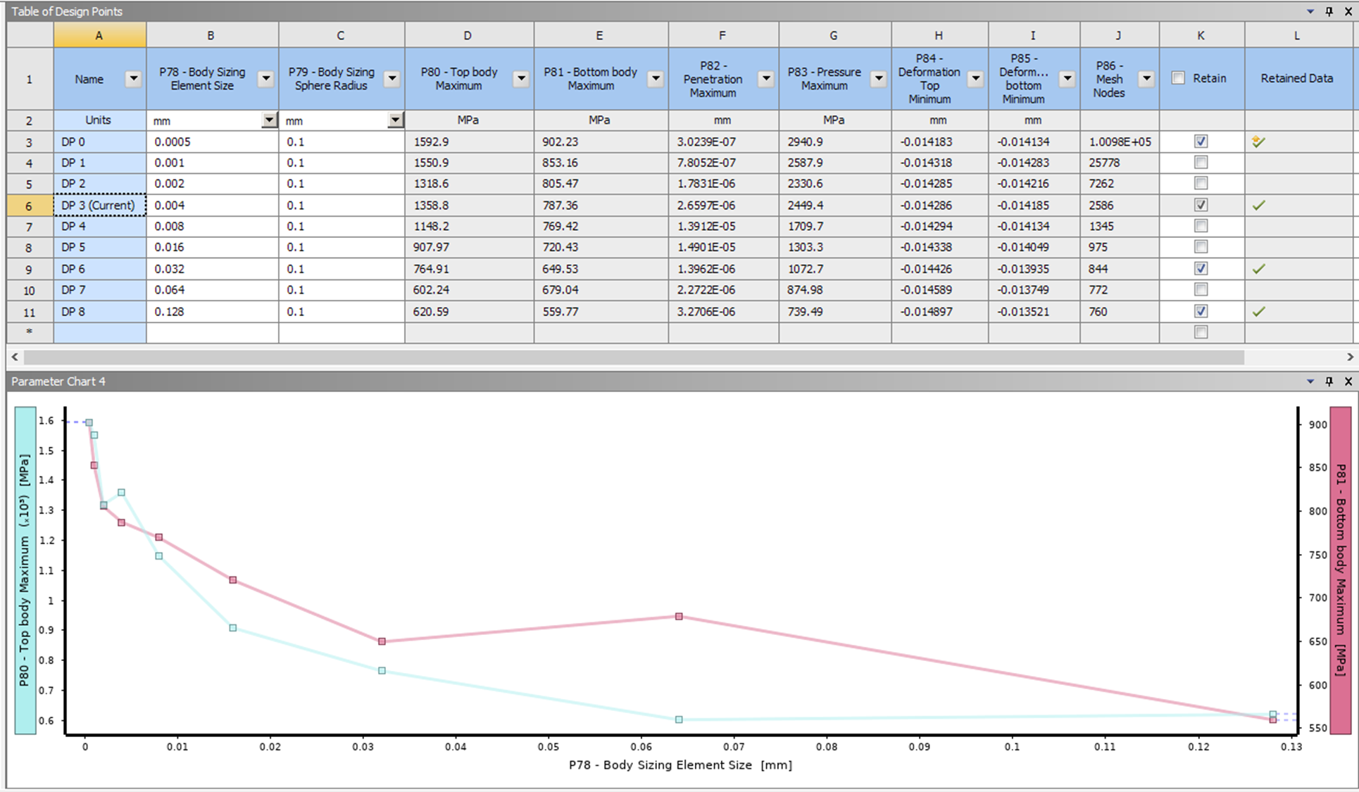
As you can see stress are highly depend upon penetration tolerance also the formulation method.
I would really appreciate If you can suggest what should be the approach or conclusion I can draw from here?
November 22, 2021 at 6:00 pmpeteroznewman
SubscriberA good starting point for mesh refinement study would be to have an element size of about 1/10 of the corner radius. Since you have all these sizes already set up, you could simply change the corner radius to 0.4 mm and just run DP0 through DP3 to look at the plot of those 4 points for Normal Lagrange.
Another refinement is to change the Detection Method of the contact to Nodal Normal to Target, assuming the Target is the flat surface.
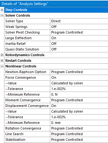
Did you change the Analysis Settings to request tighter Force and Displacement Convergence tolerances than the default 0.5%?
 November 23, 2021 at 10:42 pm
pramod1314
SubscriberThank you for the reply.
I have made following changes:
1) Force and Displacement Convergence tolerance to 0.01
2)Detection Method of the contact to Nodal Normal to Target
3) Method: Normal Lagrange
4) I changed vertex blend /fillet radius and also changed the mesh size to keep almost 10 elements in each iteration (as you suggested).

I can see the results are close to each other but the stress values are very high.
Can I trust these values?
Augmented Lagrange gives the value in the range of 700 Mpa if penetration tolerance is program controlled (penetration is 1 % of deformation).
November 24, 2021 at 12:39 ampeteroznewman
SubscriberI didn't explain myself clearly enough. When I suggested a 0.4 mm corner radius which would have 10 elements around it at an element size of 0.04 mm, I meant that the 0.4 mm blend radius would remain fixed at that value, while the number of elements would increase around the blend as the element size became smaller and smaller.
This is a Mesh Independence Study. For a fixed geometry, what element size is needed to get a stress result that doesn't change.
Discard the results you have and run a study at a fixed P87 - VertexBlend2 size of 0.4 mm
I also said that mesh independence studies use a fixed ratio of element size. Using the ratio of 2, the element size sequence is 0.04, 0.02, 0.01, 0.005, 0.0025, 0.00125.
That sequence should show the mesh independent value of stress for the Top and Bottom parts at a Vertex Blend size of 0.4 mm.
If you want to see the stress at a smaller Vertex Blend, then you would rerun the study at some other fixed value of Vertex Blend.
November 24, 2021 at 12:46 amNovember 24, 2021 at 12:53 ampeteroznewman
SubscriberYou can start with the current blend radius shown. Start the element size at 1/10 of that radius and divide it by 2 five times then plot those six points.
Viewing 9 reply threads- The topic ‘Singularity at sharp corner How to deal?’ is closed to new replies.
Ansys Innovation SpaceTrending discussions- Problem with access to session files
- Ayuda con Error: “Unable to access the source: EngineeringData”
- At least one body has been found to have only 1 element in at least 2 directions
- Error when opening saved Workbench project
- Geometric stiffness matrix for solid elements
- How to select the interface delamination surface of a laminate?
- How to apply Compression-only Support?
- Timestep range set for animation export
- Image to file in Mechanical is bugged and does not show text
- SMART crack under fatigue conditions, different crack sizes can’t growth
Top Contributors-
1191
-
513
-
488
-
225
-
209
Top Rated Tags© 2024 Copyright ANSYS, Inc. All rights reserved.
Ansys does not support the usage of unauthorized Ansys software. Please visit www.ansys.com to obtain an official distribution.
-
The Ansys Learning Forum is a public forum. You are prohibited from providing (i) information that is confidential to You, your employer, or any third party, (ii) Personal Data or individually identifiable health information, (iii) any information that is U.S. Government Classified, Controlled Unclassified Information, International Traffic in Arms Regulators (ITAR) or Export Administration Regulators (EAR) controlled or otherwise have been determined by the United States Government or by a foreign government to require protection against unauthorized disclosure for reasons of national security, or (iv) topics or information restricted by the People's Republic of China data protection and privacy laws.

