-
-
July 28, 2021 at 2:57 pm
D_P
SubscriberDear all,
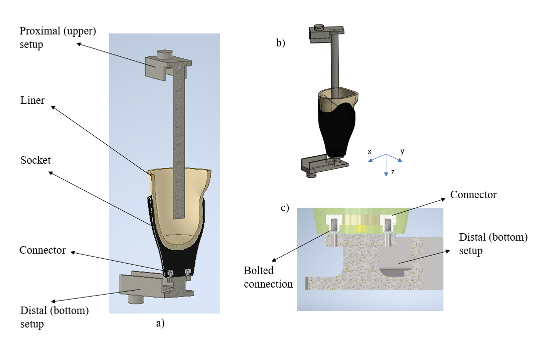
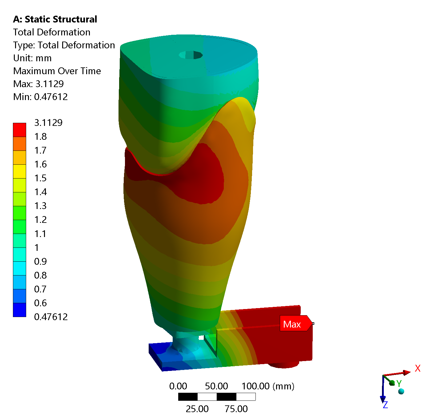
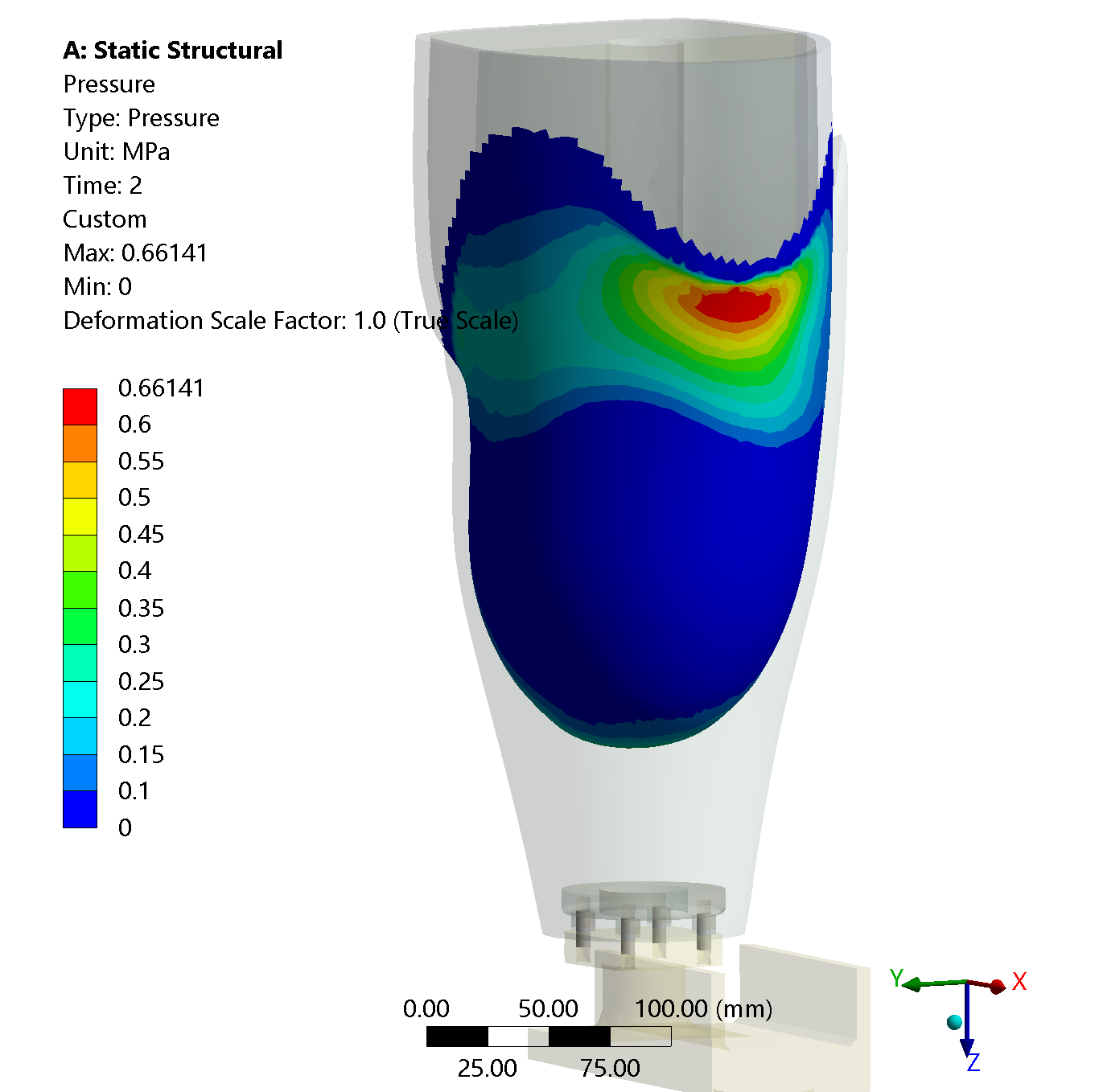
Hereunder there is the model that I am studying with ANSYS WB version 19.3.
There are two loading faces (similar to a cup): one at the top and one at the bottom. Each of these faces have constraints while the load is applied only on the bottom face. In short:
- Top face - Remote displacement (Hinge -> x,y,z,Rz=0; Rx,Ry=free)
- Bottom face - Remote displacement (Roller -> x,y=0; z,Rx,Ry,Rz=free)
- Bottom face - Load (Fx,Fy=0; Fz = ramp from 0 to 4394N)
The hinge and the roller should work as spherical joint where the two cup can swipe. The remote displacements are applied to remote points joined to the internal side of the cups (one Remote Point for each cup), while the load is applied directly on the face of the bottom cup.
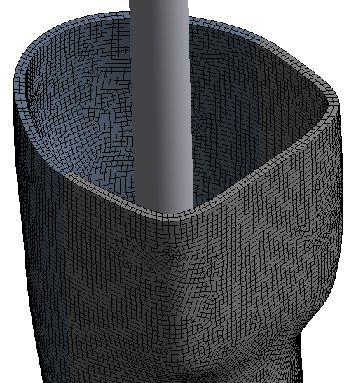
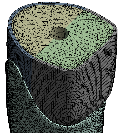
All the other parameters and the explanation of the model
are showed in the images:
August 3, 2021 at 12:57 pmAshish Khemka
Forum Moderator
What is the error message you see in the Solution Information? It may help to comment further.
Regards Ashish Khemka
August 3, 2021 at 6:32 pmD_P
Subscriber
Thank you for the answer. There is no error on which I can start debugging, only few warnings and note.
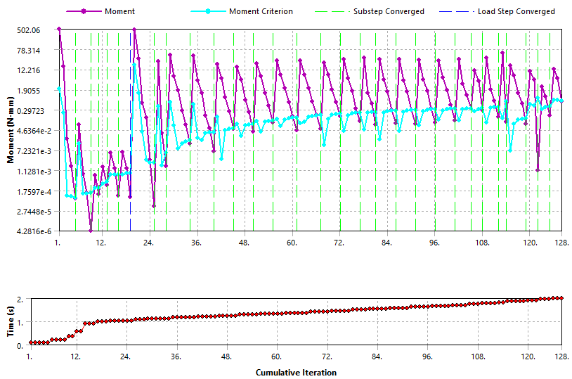
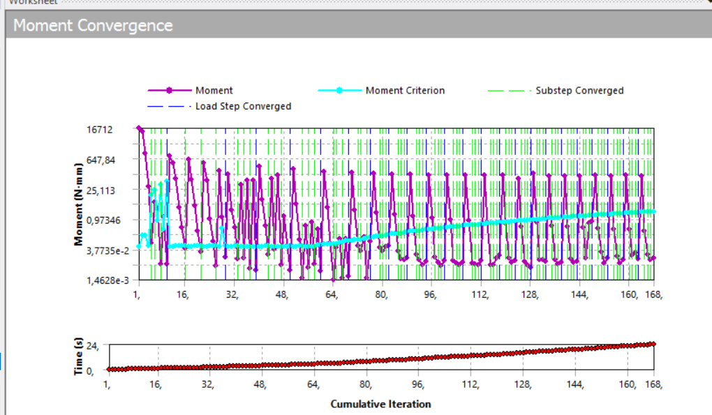
Here you have two screenshot of the Moment Convergence: the first is when the simulation converged, meanwhile the second is what it is happening now until I stop the simulation. The simulation parameters are exactly the same and I do not understand why it doesn't work.
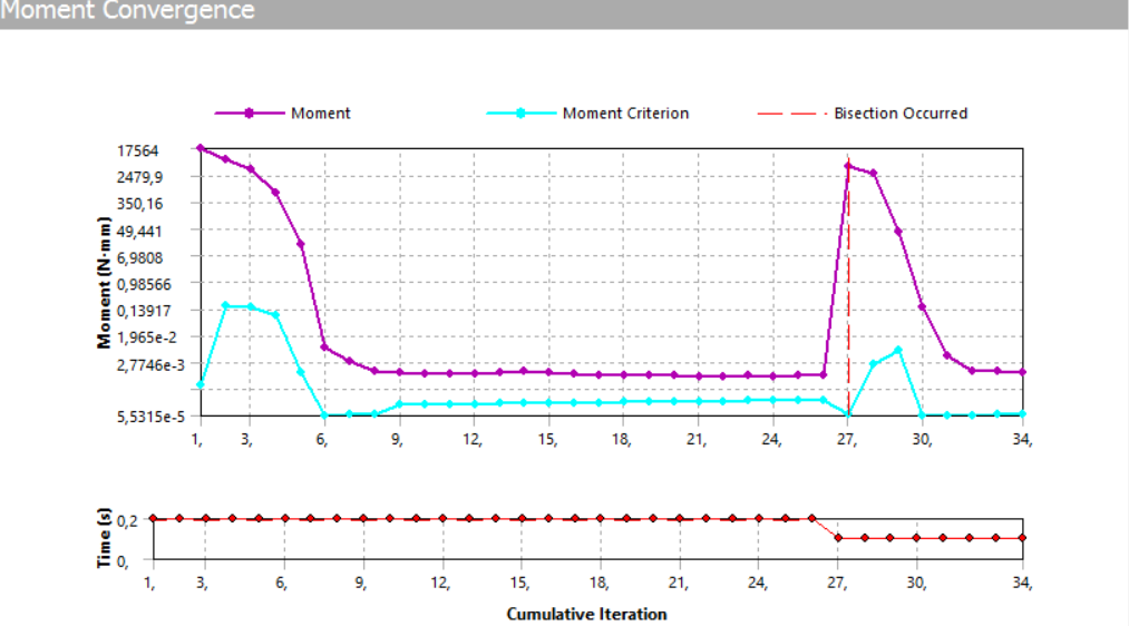 I tried to change the mesh and with a coarse mesh it starts to converge after several bisections. Hereunder there is the screenshot of the moment convergence with coarse mesh.
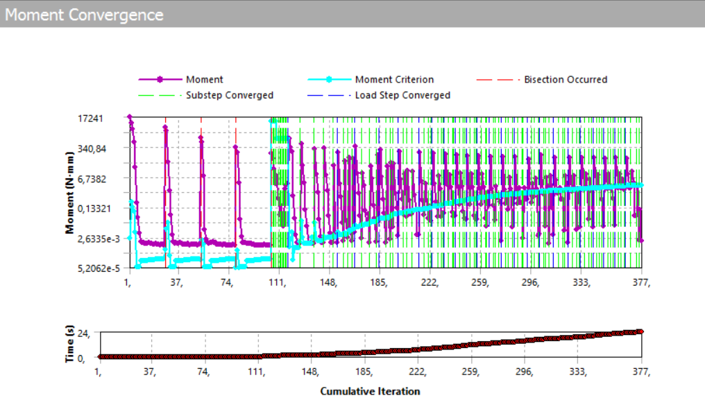 This is what I have. I would be very glad if you have any suggestions or ideas.
Thank you in advance.
Best regards Daniele
August 3, 2021 at 7:56 pmpeteroznewman
SubscriberDear Daniele Click on the Solution Information folder and in the Details window, type the number 3 into the Newton-Raphson Residuals field.
Restart the solution and allow three more iterations to solve (or just run the solution from the beginning).
Under the Solution Information folder will be 3 N-R Force Residual plots. Look at the location of the maximum value. That is where you may need to have a refined mesh.
Do you have any linear elastic materials with a Poisson's Ratio above 0.45? Those can cause convergence issues which may be improved by turning on mixed u-P element formulation and changing the material to a hyperelastic material model.
Regards Peter
August 4, 2021 at 1:44 amAshish Khemka
Forum ModeratorHi Daniele What did change between the model that was converging earlier and the model with convergence issues?
Regards Ashish Khemka
August 4, 2021 at 2:15 ampeteroznewman
SubscriberCiao Daniele What version of ANSYS are you using?
I downloaded your archive and opened it. I see the number of nodes and elements (306k, 248k) are too large for the Student license. Fortunately, I have a full license for 2020 R1. Unfortunately, if you are using an older version, you won't be able to open my archive.
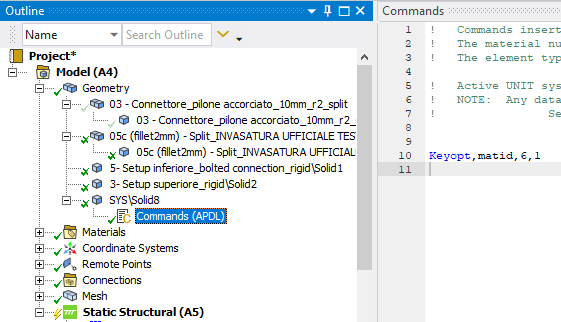
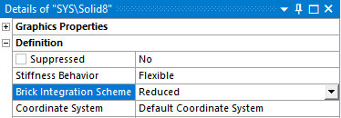
Now that I have opened the archive, I see you are using hyperelastic materials. The inner liner part is modeled with Silicon Rubber. That would benefit from Keyop(6)=1 that would turn on the mixed u-P element formulation and the reduced integration scheme. The keyop is done by a Commands object and looks like this:
 In the details window, change the Brick Integration Scheme to Reduced.
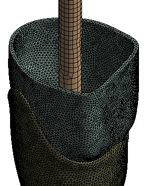
 It is generally unacceptable for solid elements to have only one element through the thickness, and that is the condition on the inner liner part.
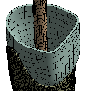 A minimum of two elements through the thickness is required and more is better. With some effort, the inner liner part could be made using hex elements which would reduce slightly the number of elements.
 Since the steel parts are much stiffer than the nylon and silicon parts, change the steel parts to rigid behavior to use fewer nodes and elements.
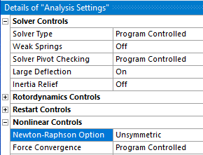
This model has a large Coefficient of Friction. The solver issues a message to say
 You can do that under Analysis Settings, but that is only needed if the convergence is failing. If it solves with the Program Controlled setting, that is a slightly faster solver.
 One of the best changes you can make to this model is to not use 24 steps, but use 2 steps. Step 1 is to tighten the bolts. Step 2 is to apply the force. The the Step Controls can be Auto Time Stepping On.
Looking at the Bonded Contact between the steel shaft and the inside of the inner liner. I would have modeled the resin as solid elements instead of using beam elements to connect nodes on the shaft to nodes on the inside of a very soft silicon rubber material.
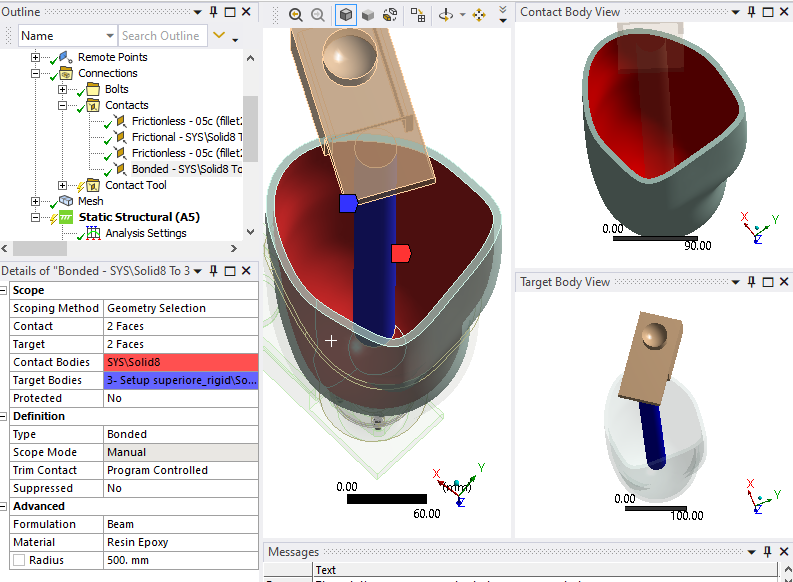 In a few clicks, you can do a Volume Extract in SpaceClaim to model the epoxy resin.
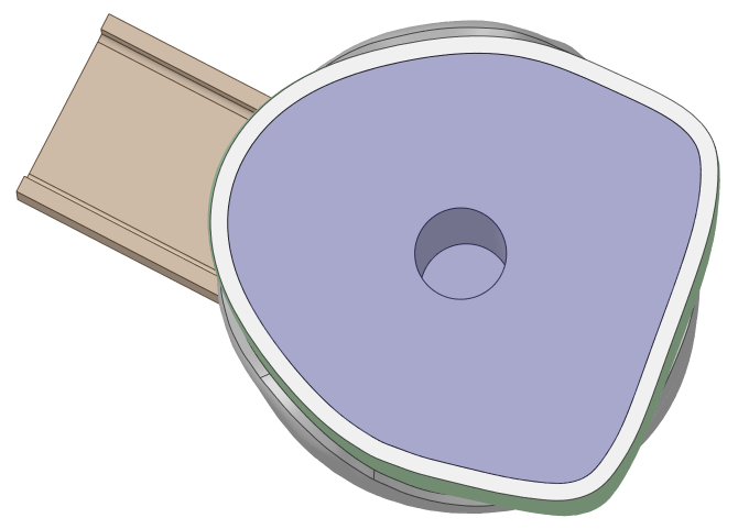 Drag the solid out of the Volume component, and put it next to Solid8, hide the other components and use the Share button on the Workbench tab to avoid having to use Bonded Contact.
August 4, 2021 at 4:28 amAugust 4, 2021 at 10:43 pmAugust 5, 2021 at 12:35 ampeteroznewman
SubscriberDear Daniele I see you said you are using ANSYS 2019 R3 which I couldn't use as the problem size exceeds the Student license limit.
I built the model using ANSYS 2020 R1 which you can't open.
I am willing to help you do what I did using 2019 R3. If you would like to meet on Skype, please reply with an email address.
Best regards Peter
August 5, 2021 at 2:38 ampeteroznewman
SubscriberThe solution above that took 3 hours and 6 minutes used the Unsymmetric solver, but I didn't know if that was a necessary intervention.
I reran the solution using the Symmetric solver, which is the Program Controlled default and it only took 2 hours and 12 minutes. So anyone using the archive attached above should change back to the Symmetric solver and save themselves some time waiting for the solution.
August 5, 2021 at 3:35 pmD_P
SubscriberCiao :D
Thank you so much for your help and especially for your time in solving this problem! I followed your advices and now the simulation seems to get better although there are still some problems. I do not want to waste your time but I would be delighted to have a talk with you!
Dear I did not change anything between the two analysis. I took the converged analysis, cleared the generated data and ran it again.
I thank both of you for your support.
Regards Daniele
August 5, 2021 at 4:19 pmpeteroznewman
SubscriberCiao Daniele We will set up a time to talk.
Regards Peter
Viewing 11 reply threads- The topic ‘Convergence issue on Static structural analysis. Help?’ is closed to new replies.
Innovation SpaceTrending discussionsTop Contributors-
4838
-
1587
-
1386
-
1242
-
1021
Top Rated Tags© 2026 Copyright ANSYS, Inc. All rights reserved.
Ansys does not support the usage of unauthorized Ansys software. Please visit www.ansys.com to obtain an official distribution.
-
The Ansys Learning Forum is a public forum. You are prohibited from providing (i) information that is confidential to You, your employer, or any third party, (ii) Personal Data or individually identifiable health information, (iii) any information that is U.S. Government Classified, Controlled Unclassified Information, International Traffic in Arms Regulators (ITAR) or Export Administration Regulators (EAR) controlled or otherwise have been determined by the United States Government or by a foreign government to require protection against unauthorized disclosure for reasons of national security, or (iv) topics or information restricted by the People's Republic of China data protection and privacy laws.

