Tagged: cinvestav, guest article, SCADE, scade rapid prototyper, scade suite, scade test, student
-
-
September 6, 2024 at 2:23 pm
 SolutionParticipant
Guest Article – Student – Traffic Light Control with SCADE
This article is a guest contribution from Cinvestav. It was written by a student group as part of Masters-level, semester long SCADE academic program course.
It explains the design and simulation of a system that controls the traffic light system of a four-way intersection with emergency vehicle priority.
If you are an academic and are interested in teaching an engineering curriculum backed by Ansys tools, please have a look at our Ansys Funded Curriculum page.
Summary
The Intelligent Traffic Light System project addresses the need for improved emergency vehicle response times in urban environments. By utilizing transmitters and receivers to detect the presence of emergency vehicles (e.g., ambulances or patrol cars) in specific lanes, the system dynamically adjusts traffic light timings. Specifically, it prioritizes the passage of emergency vehicles by turning the light green for the lane in which they are present, facilitating their passage through intersections.
This project was developed with the ANSYS SCADE Suite software, and its principal objective is to demonstrate the feasibility and advantages of integrating intelligent traffic management systems to prioritize emergency vehicle access while maintaining efficient overall traffic flow. The system’s sensors detect emergency vehicles and adjust the light sequence accordingly, ensuring that emergency response times are minimized without disrupting normal traffic operations. Through this adaptive mechanism, the project aims to enhance urban mobility and safety, setting a new standard for intelligent traffic management in modern cities.
System Description
System Interface
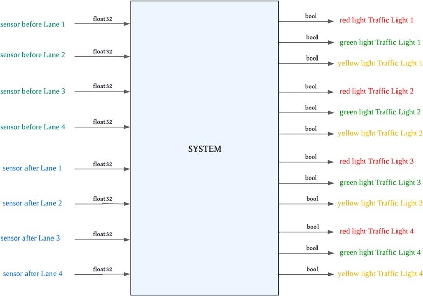
The system receives the signals of two sensors for each lane; one of them named as
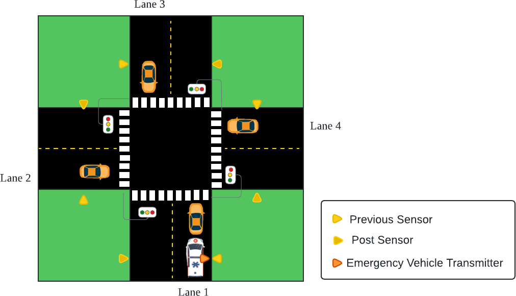
beforeSensoras it is placed before its corresponding lane Traffic Light, when it is triggered, it means the presence of a new emergency vehicle in that specific Lane. The other sensor is namedafterSensor, referring to it being placed after its corresponding Traffic Light, when it is triggered, the system takes it as the exit of an emergency vehicle, not necessarily from its own Lane. In exchange, the system delivers the red, green and yellow lights of each Traffic Lane, always having one of those three lights on, but never having more than one green light on at the same time.Here is a simple diagram that explains the expected placement of traffic lights and sensors in the environment planned for the system:
The next image explains the system’s interface, having already explained its inputs and
outputs:
System Behavior
The traffic light system incorporates sensors capable of detecting emergency vehicles and adjusting the traffic signal pattern to ensure that the emergency vehicle’s lane has priority over the other ones. This system’s behavior provides a solution for emergency response while preserving the normal operation when no emergency vehicles are detected. Some of the principal functionalities of the Traffic Light Intersection are:
- The system shall work on a 4-lane intersection with 4 traffic lights, one for each lane.
- The emergency vehicles shall use transmitters that the sensors placed on the street can detect.
- The system shall use sensors placed before and after the traffic lights to detect the presence of emergency vehicles in dedicated lanes.
- The system shall detect the presence of an emergency vehicle when it triggers a sensor placed before the traffic light.
- The system shall consider that an emergency vehicle has passed when it triggers a sensor placed after a traffic light.
- The system shall prioritize the passage of emergency vehicles by turning green the traffic light when these vehicles are present.
Architecture
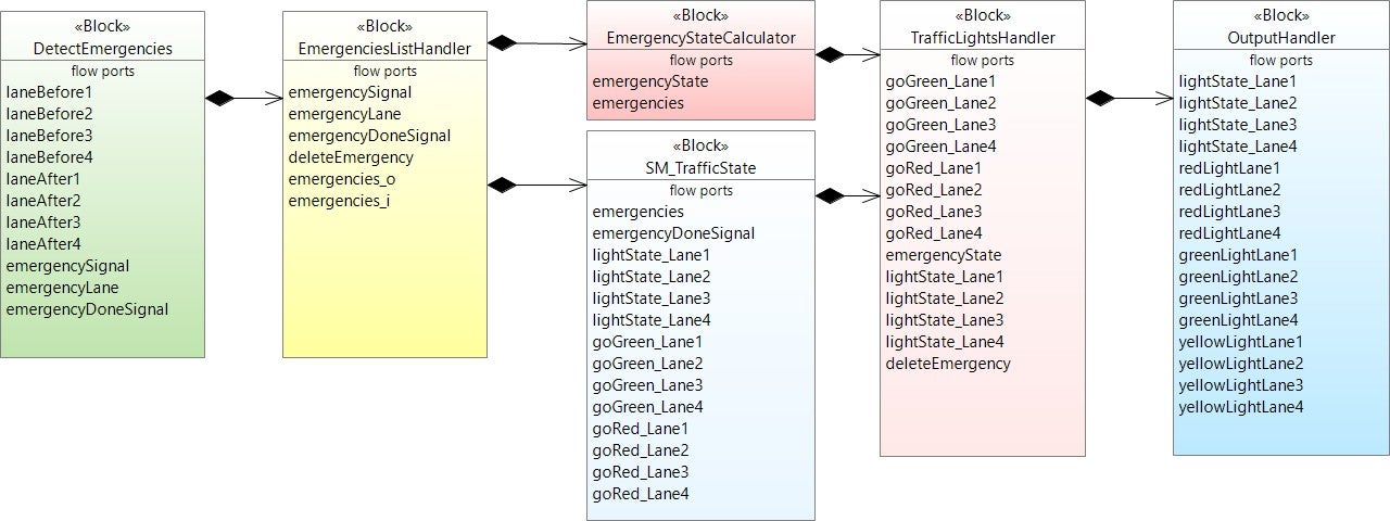
The system is designed with several interconnected blocks. Each block performs a critical role in controlling and coordinating the traffic lights, ensuring efficient traffic flow and appropriately prioritizing emergency vehicles. Internal communication between these blocks is critical in determining the current status of each traffic light and dynamically adjusting it according to traffic conditions and signals received from emergency vehicles.
The system architecture diagram shows how these blocks interact with each other to manage emergency vehicle detection, prioritization and synchronization of traffic light changes.
Below is a diagram illustrating the existing components of the system and the relationships between their inputs and outputs. This diagram provides a clear view of how each block within the system interacts with the others, showing the necessary connections and data flows for its operation.
Each block in the diagram represents an essential part of the system, and their interactions reflect the logical sequence of operations that allow the prioritization of emergency vehicles in the intelligent traffic light system. By understanding these relationships, one can better grasp the overall design of the system and the mechanisms that ensure its efficiency and effectiveness.
Software Requirements
There are twenty Software Requirements, which have been categorized in the functions the software will have to fulfill under different circumstances. These categories are:
- Standard behavior: This section of requirements describes the normal state of the system in which no emergency is present, it details the behavior of each traffic light independently by using states.
- Single emergency behavior: This section of requirements describes the system when only one emergency is currently occurring, so the lane of this emergency must be prioritized.
- Multiple emergencies behavior: This section of requirements describes the behavior of the system when there are two or more emergency vehicles at the same time in different lanes, these emergencies are attended in order of their arrival, because these lanes must be vacated as quickly as possible, the time limit to pass is not as long as when there is only one emergency.
- Emergencies Attended: This section of requirements describes the process that is carried out when an emergency has finished: it can be either because an ambulance has already left a lane or the time limit for it to pass has elapsed.
Once the software requirement categories are specified, some examples of the requirements of each of them will be listed:
Standard behavior
REQ TL_SB_01: When it’s booted for the first time, the system shall display red at the four traffic lights by default.
REQ TL_SB_03: While one of the traffic lights is on green or yellow light, the rest of the traffic lights shall maintain a red light until commanded.
REQ TL_SB_08: When there are no current emergencies and the system detects one emergency vehicle incoming, the traffic light that’s currently on green light shall change immediately to a yellow light and after 5 seconds it shall turn into a red one.
Single emergency behavior
REQ TL_SEB_01: The system shall be able to detect in which lane an input sensor has been activated by an emergency vehicle.
REQ TL_SEB_03: The system shall be able to detect an emergency vehicle only once, even if the vehicle stays in front of the sensor for a long period of time.
REQ TL_SEB_04: When there are no current emergencies and the system detects one emergency vehicle, the system shall focus on setting the emergency lane into a green light.
REQ TL_SEB_05: While there is one current emergency, the time of each green light of all traffic lights shall be 80 seconds.
Multiple emergencies behavior
REQ TL_MEB_01: The system shall register the lanes where there’s been an unattended emergency.
REQ TL_MEB_02: While there is more than one emergency, the time of each green light of all traffic lights shall be 60 seconds.
Emergencies attended elements
REQ TL_EA_01: When a post-signal emergency vehicle is received and there are multiple emergencies, the traffic light currently in green shall change to yellow and then to red. REQ TL_EA_02: When a post-signal emergency vehicle is received and there are multiple emergencies, the system shall focus on the next emergency to attend and set the corresponding lane into a green light.
REQ TL_EA_03: When the time limit for emergency vehicles has elapsed and there are multiple emergencies, the system shall focus on the next emergency to attend and set the corresponding lane into a green light.
Software Model Description
The next part of the article will describe in detail which operators were used to provide a solution compliant of the project’s system and software requirements.
Constants and Data Types
DATA TYPES
SCADE Suite’s data types can be broadly divided between two kinds: predefined and user defined.
The following table depicts the Traffic Light System user-defined data types:
Type Definition Enum Values EmergencyState enum[NORMAL, SINGLE_EMERGENCY, MULTIPLE_EMERGENCIES]LaneNumber enum[LANE1, LANE2, LANE3, LANE4, NONE]LightType enum[RED, YELLOW, GREEN]Emergencies LaneNumber^4 (array)CONSTANTS
Constant values that will be consistently used within a system are documented in this section, as depicted in the following Table.
Name Data Type Value FREQUENCY int6450000000GREEN_LIGHT_DEF int6410SENSOR_MIN float323.5TIME_LIMIT_MULTIPLE int6410TIME_LIMIT_SINGLE int6415YELLOW_LIGHT_DEF int645EMPTY_EMERGENCY Emergencies[NONE, NONE, NONE, NONE]Software Model Operators
CALL GRAPH
The tree of the model operators is shown in the call diagram below, the operator
“TopIntersection” is the root operator.
1. TrafficLight
1.1 TopIntersection
1.2 BasicBlocks1.2.1 Counter
1.2.2 EdgeDetector1.3 INOUT_Handler
1.3.1 InputRegulator
1.3.2 OutputHandler
1.3.3 StateToRGB1.4 Emergency_Handler
1.4.1 DetectEmergencies
1.4.2 EmergencyVehicleDetector
1.4.3 WhichLane1.5 EmergenciesList_Handler
1.5.1 AddToListEmergencies
1.5.2 AttendNextEmergency
1.5.3 DeleteFromListEmergencies
1.5.4 EmergencyListHandler
1.5.5 EmergecyStateCalculator1.6 TrafficLights_Handler
1.6.1 SM_TrafficLightState
1.6.2 TrafficLightHandler1.7 Intersection_Controller
1.7.1 IntersectionController
1.7.2 SM_TrafficStateTOP INTERSECTION OPERATOR
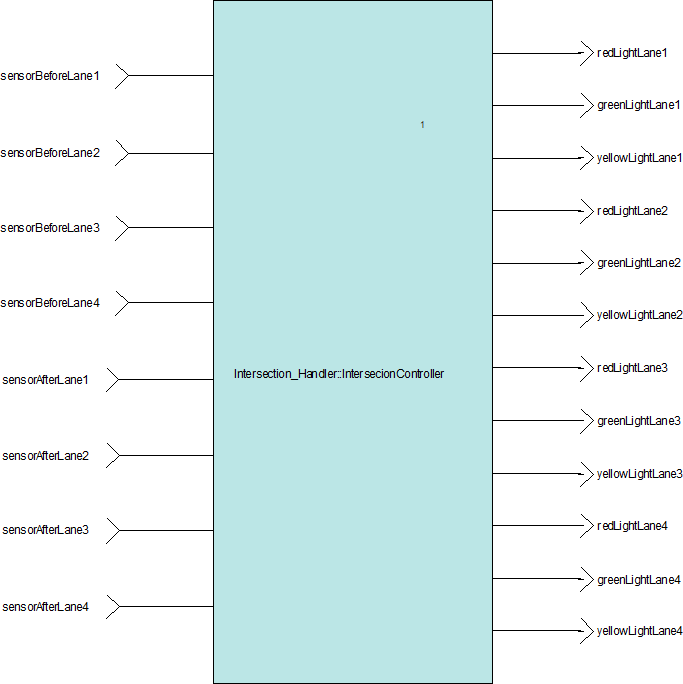
This operator is the interface of the system, in other words, it contains its inputs and outputs, which have been already explained earlier.
INTERSECTION CONTROLLER OPERATOR
This module connects the system’s principal operators, its main function is to integrate the different
modules to ensure that they work together effectively.
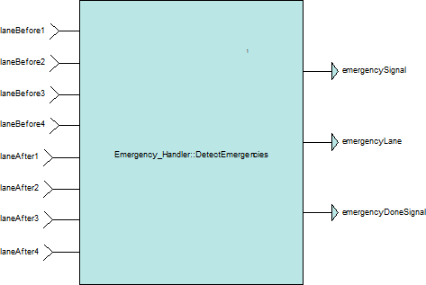
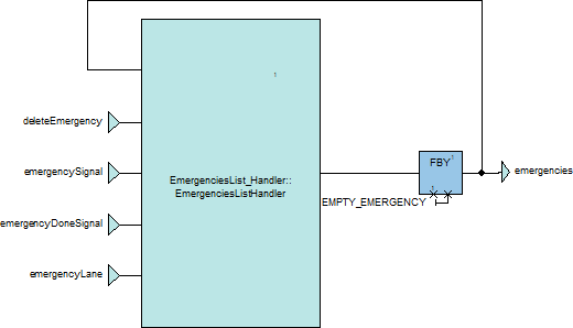
DetectEmergencies receives the outside sensors and delivers the flags that denote when and from which lane an emergency vehicle has been detected. EmergenciesListHandler updates the list of emergencies unattended whenever an emergency vehicle has been detected entering or exiting the intersection.
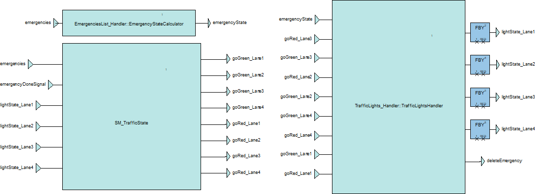
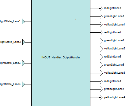
SM_TrafficState and TrafficLightsHandler work in a symbiotic, reciprocating way. The first one is a state machine that receives the current state of the traffic lights and sends the signals in charge of changing them, the second one receives these signals and acts correspondingly, sending back the current state of the traffic lights. These states are also sent outside of the system by OutputHandler.
SM_TRAFFIC STATE OPERATOR
All traffic lights need a signal to know when to change from red to green or green to red, so this module controls when these signals are activated, this module is necessary to synchronize all the lights and make sure that each change is executed correctly.
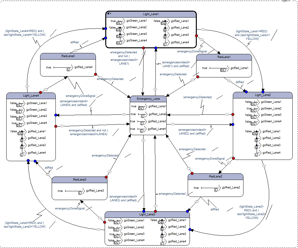
This module has a state machine with 4 main states LightLane1, LightLane2, LightLane3 and LightLane4, a transition state Emergency_Lane and a state that sets every light to red in special cases.
Every main state represents one of the four traffic lights, inside of every state, its own signal to go to green is activated and the signals of the other traffic lights are deactivated, also the signals to go to red of every traffic light is deactivated, this is for be prepared to activate these signals in other states.
The normal behavior of the system is a cyclic clockwise order, this means that every traffic light has a turn to be green and only changes to the next traffic light when the current traffic light has just changed to red.
When an emergency is detected, the system uses the transition state, this state is a connection between all states and set every light to red before entering to any other state, and similar to this transition state, every main state has a state that sets their own light to red, and continues only when all the lights are red.
This module has an array that contains the list of emergencies and a signal that indicates when a new emergency has been detected.
This module has an output that indicates the current state of each traffic light, it can be RED, YELLOW or GREEN.
TRAFFIC LIGHT HANDLER OPERATOR
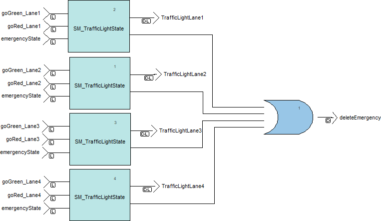
This module controls the inputs and outputs of the state machine of each traffic light, it has all the inputs that every traffic light needs, the signal goGreen to set the green light, the signal goRed to set the red light and the emergencyState signal that indicates if there is a current emergency in the system.
Also, it has every state of all the traffic lights as a output and a signal that indicates if a traffic light green time limit has elapsed to delete an emergency in that case by the output deleteEmergency.
STATE MACHINE TRAFFIC LIGHT OPERATOR
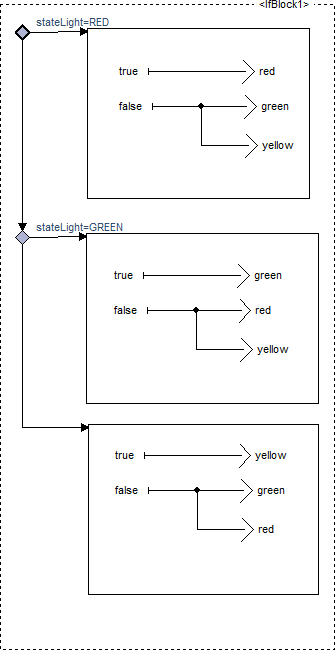
This module controls the state of one traffic light, it contains a state machine with red, yellow and green states. The initial and main state is the Red state, it only goes to green state when it is indicated with the goGreen input signal, it stays in that state for a period of time set by the current state of the system using the emergencyState input, if there is an emergency, the time in green will be longer, if there is more than one emergency, the time in green returns to normal, the green state can be interrupted by the input signal goRed, is important to specify that before set the traffic light to red, it is set to yellow first. The traffic light is going to turn red again after a period set by the constant YELLOW_LIGHT_DEF. Also, this module can send a signal when the green time has done using the emergencyGreenDone output.
EMERGENCY STATE CALCULATOR OPERATOR
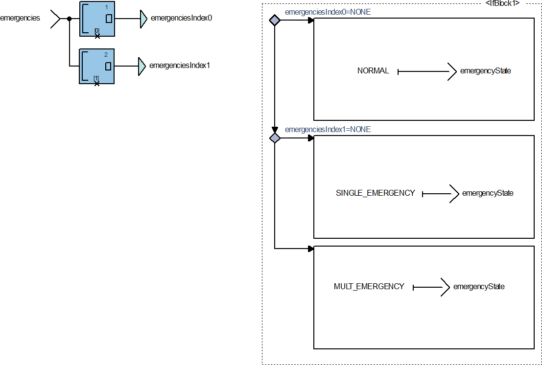
This module performs the task of determining the state of the system, the system can be in three states, NORMAL, SINGLE_EMERGENCY and MULTIPLE_EMERGENCIES, this is especially useful for determining the green light time period at any time.
The module has the list of emergencies as an input, if the firs element is empty, the current state is NORMAL, if the first element is not empty, the current state is SINGLE_EMERGENCY, and if the first and second element are not empty, the current state is MULTIPLE_EMERGENCIES.
ATTEND NEXT EMERGENCY OPERATOR
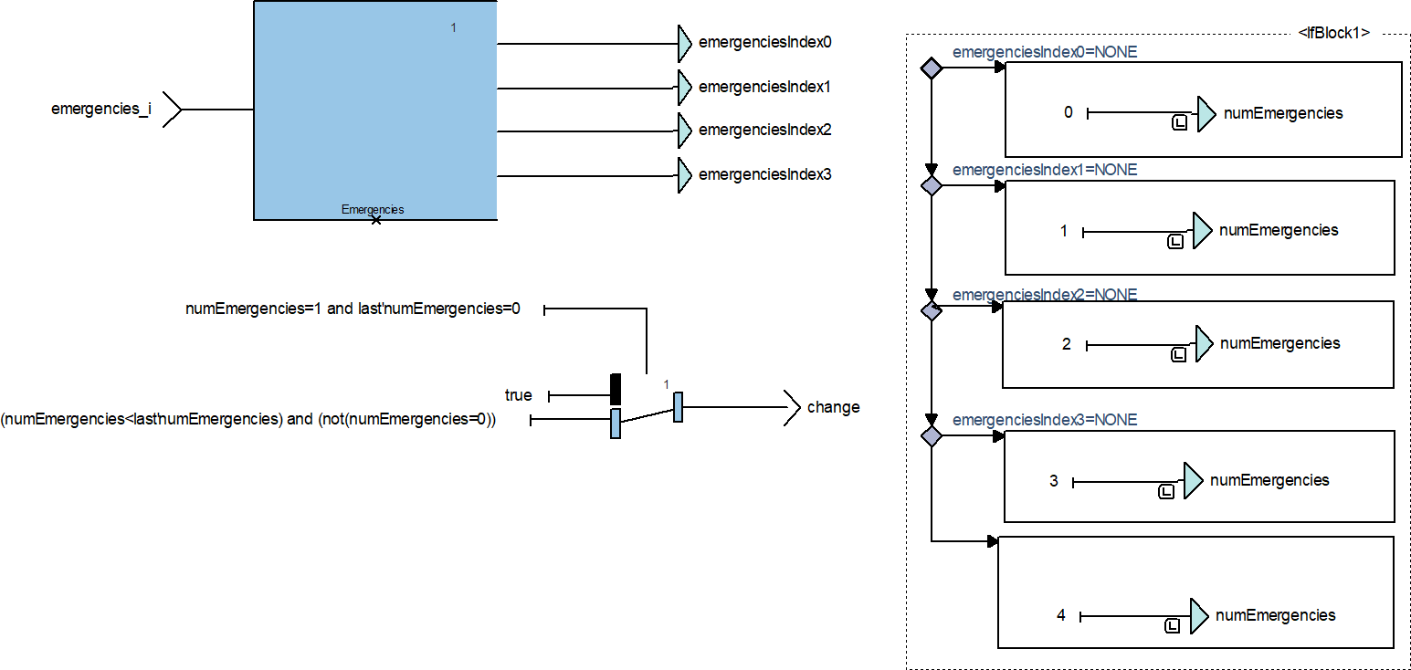
This module has the function of signaling when the system must focus on the next emergency to be attended. This flag can be raised either when there were no emergencies and one has just appeared, or when there are multiple emergencies, and one has already been handled, leaving room for the system to focus on the next one.
The module receives the list of emergencies, analyses the current and last number of emergencies in the system and sets a flag to true when one of the cases already mentioned happens.
EMERGENCY LIST HANDLER OPERATOR
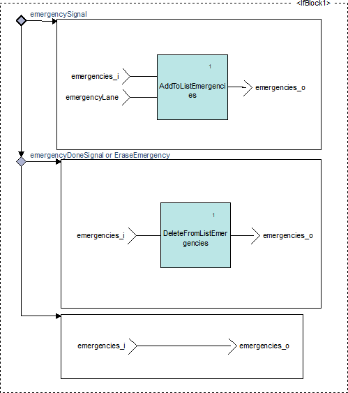
This module has the function to manipulate the system’s list of emergencies, adding or erasing one as received signals command it. It receives the boolean inputs emergencySignal, mustEraseEmergency and emergencyDoneSignal. If the first one has a true value, the module will enable AddToListEmergencies and add the value of emergencyLane at the end of the List. If mustEraseEmergency or emergencyDoneSignal are true, the module will enable DeleteFromListEmergencies allowing the list to erase its first element and roll the other ones.
DELETE FROM LIST EMERGENCIES OPERATOR
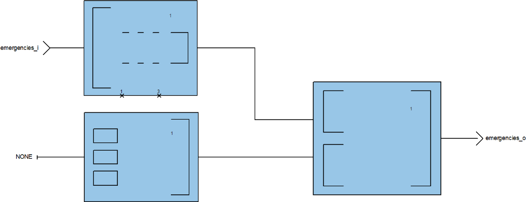
This module, whenever it is enabled, has the function to delete the first emergency from the emergencies list. It receives the list and takes only its last three elements, adding a new one with the value of NONE at the end of it. Simulating the behavior of a FIFO list.
ADD TO LIST EMERGENCIES OPERATOR
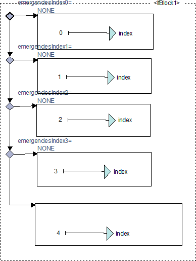
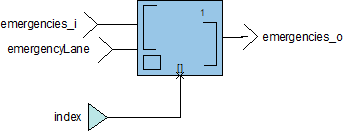
This module has the function of registering the next emergency that is detected, it will save the line in which the emergency occurs knowing where it was saved in order of how the emergencies are arriving.
It imitates a FIFO list behavior so the system can always access the first element to attend the next emergency or check if there are any emergencies at the moment.
This module has the current list of emergencies as an input and a data type
emergencyLane, that indicates the line where the emergency was detected.
The module has an array output that indicates the new list of emergencies with the last emergency detected added.
DETECT EMERGENCIES OPERATOR
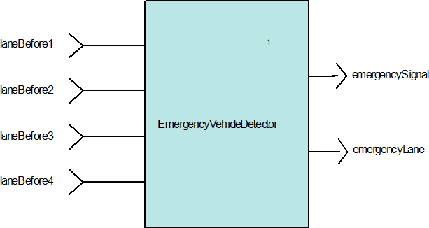
This module uses the EmergencyVehicleDetector block to constantly monitor all sensors, and when a signal is detected from some of them, an emergencySignal or emergencyDoneSignal is sent to warn that an emergency was detected, also the module sends on which line it was detected a vehicle on the sensor before the traffic light using the emergencyLane output.
EMERGENCY VEHICLE DETECTOR OPERATOR
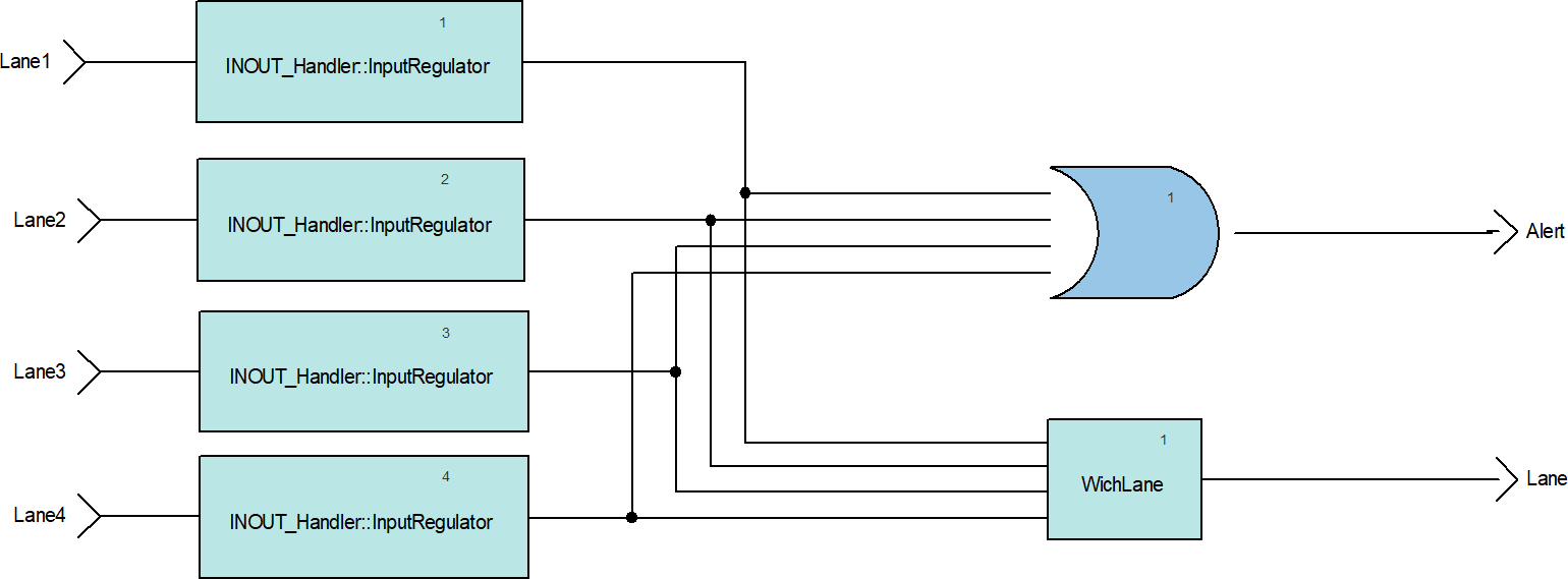
This module has four inputs that represents four sensors, the input of every sensor is modulated to have a boolean response instead a voltage level using the inputRegulator block, if there is any change detected, the module sends an output signal Alert and a data indicating the lane in which the emergency was detected.
WHICH LANE OPERATOR
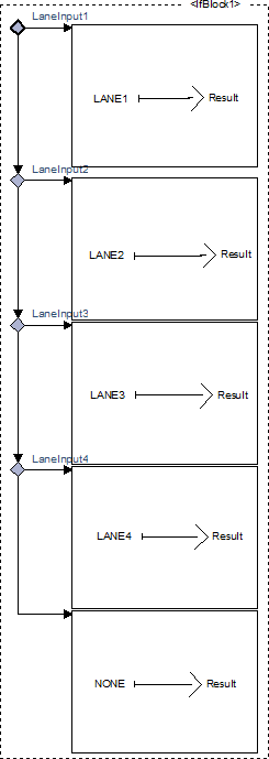
This module receives four boolean signals and sends a data type LaneNumber to indicate which of the four signals is activated.
INPUT REGULATOR OPERATOR
This module receives a data that represents a voltage level and if the input is less than the constant SENSOR_MIN, the output is false by the other hand if the input is bigger or equal than the constant, the output is true, so the module can set a range of detection for each sensor.
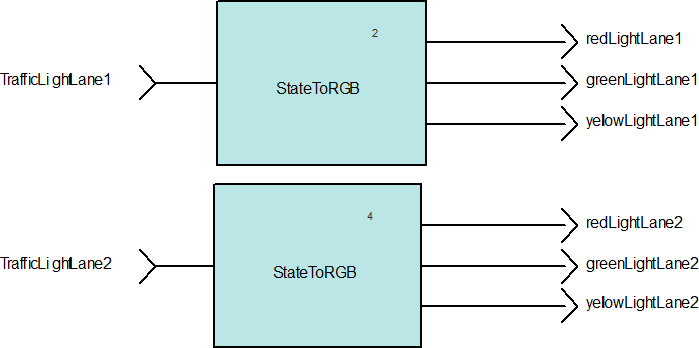
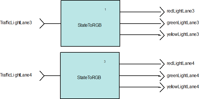
STATE TO RGB OPERATOR
The entire system has an independent state for each traffic light, so this block translates these states to its respective boolean value, because each traffic light needs three boolean values for the three lights red, yellow and green.
OUTPUT HANDLER OPERATOR
This module has the function to use four instances of StateToRGB, one for each Traffic Light, to convert the system type LighState to three booleans that indicate the whether the green, red and yellow lights of each Traffic Light must be on or off.
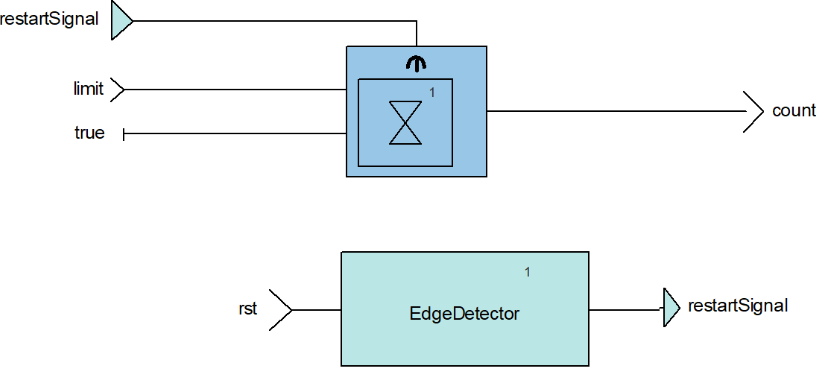
COUNTER OPERATOR
This operator is a counter used to wait for the time required for a traffic light to stay on green light and yellow light.
It has a Limit input where you enter the cycles to count, a reset input where you enter when you want to restart the counter and an output with the result of the count.
EDGE DETECTOR OPERATOR
This operator detects a rising edge on an input signal, resulting in a signal that lasts only one clock cycle, and is used for various system processes such as vehicle detection.
Verification
A critical part of the project development is to do the verification (testing and coverage) of the software. The following are two examples of the tests that were created to verify the system’s correct behavior.
#////////////////////////////////////////////////////////
# Test Case Reference :
# TL_TEST_IB_06
#Test case Objectives :
# Verify the system is able to detect emergency only once even if the emergency vehicle Stays
#  on the sensor.
#Covered Requirements :
# TL_SEB_03
#Test Case Acceptance Criteria :
# check the green light of a lane when sensorBeforeLane is 5.0 and it shall be green only the
#  specified time.
#Test case Description :
SSM::set TopIntersection/sensorBeforeLane4 5.0
SSM::cycle 15
SSM::check TopIntersection/greenLightLane4 true sustain=1
SSM::set TopIntersection/sensorBeforeLane4 0.0
SSM::cycle 15
#--------------------------------------------------------
#////////////////////////////////////////////////////////
# Test Case Reference:
# TL_TEST_IB_01
#Test Case Objectives :
# Verify that when the system is booted, the four traffic lights are in red.
#Covered Requirements :
# TL_SB_01
#Test Case Acceptance Criteria :
# Check the four lights redLightLane1, redLightLane2, redLightLane3 and redLightLane4, these
#   signals shall be true.
# Test Case Description :
SSM::check TopIntersection/redLightLane1   true
SSM::check TopIntersection/redLightLane2   true
SSM::check TopIntersection/redLightLane3   true
SSM::check TopIntersection/redLightLane4   true
SSM::cycle 5
#--------------------------------------------------------
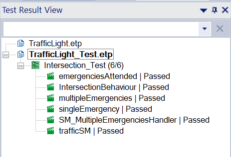
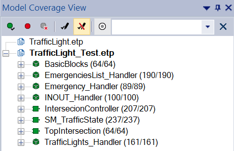
Once all the tests corresponding to the software requirements have been done, it is mandatory to execute them to know if the model of software fulfills its expected functions. After passing the tests, making the model coverage is the next step.
As can be seen in the next images, the software model passed all the tests, and the tests have a coverage of 100%
Implementation
Implementation can take two different forms, whether via simulation or via physical application.
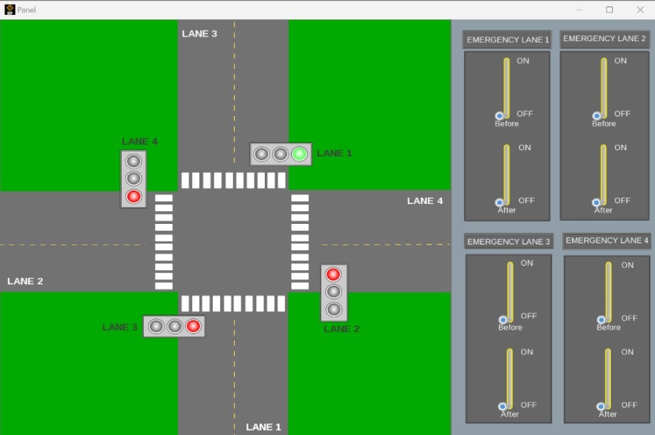
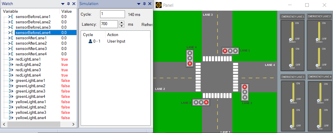
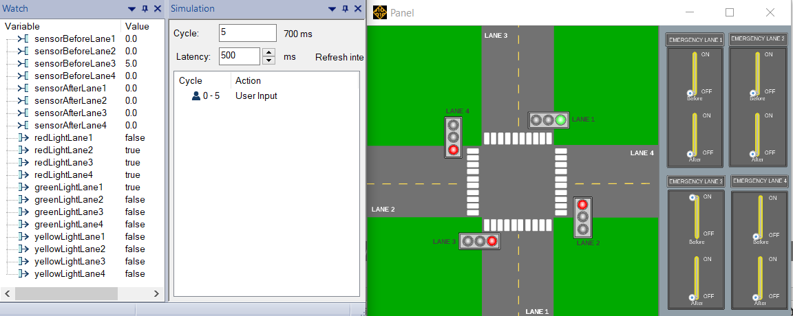
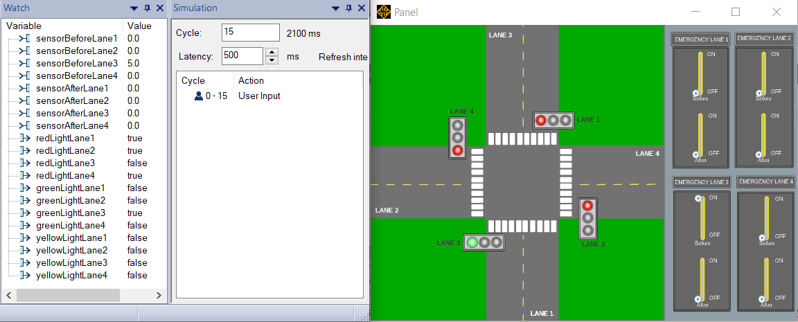
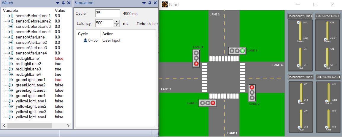
The first one can be executed with a control panel built in the tool SCADE Rapid Prototyper. The simulation shows the four Traffic Lights of the intersection and their behavior both under normal and urgent circumstances. The operator can use the switch at the right of the panel to emulate the presence of an incoming emergency vehicle by putting one of the Before levers in an ON state. Similarly, the operator can simulate the exit of an emergency vehicle by putting one of the After levers in an ON state.
There are some scenarios implemented in simulation using the panel to show some functionalities, the scenarios that are shown below are tests shown later in the article.
Scenario 1:
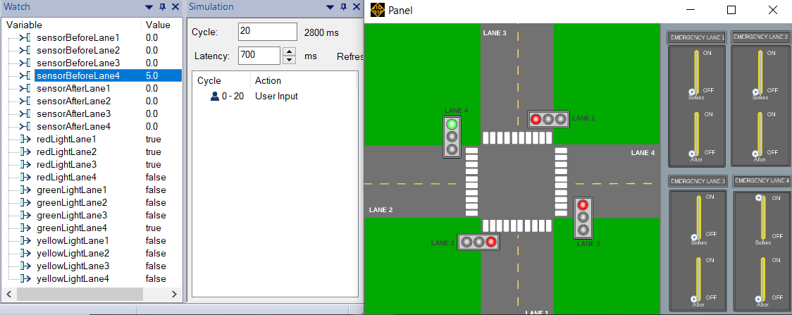
Test ID: TL_TEST_SEB_03
When an emergency is detected, the system shall set the current green light into a red light and set green the traffic light of the corresponding lane of the emergency.
After 15 cycles is set green light of the lane 4:
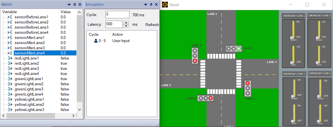
Test ID: TL_TEST_IB_01
When the system starts, all traffic lights shall be red.
Test ID: TL_TEST_MET_01
When two or more emergencies are detected, the system shall attend these emergencies in order they arrive.
After 10 cycles is set green light of the lane 3:
After 10 cycles is set green light of the lane 1:
The second kind of demonstration is the physical implementation. This one entails the use of different components, that will be listed below:
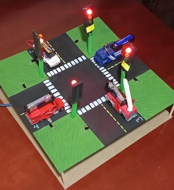
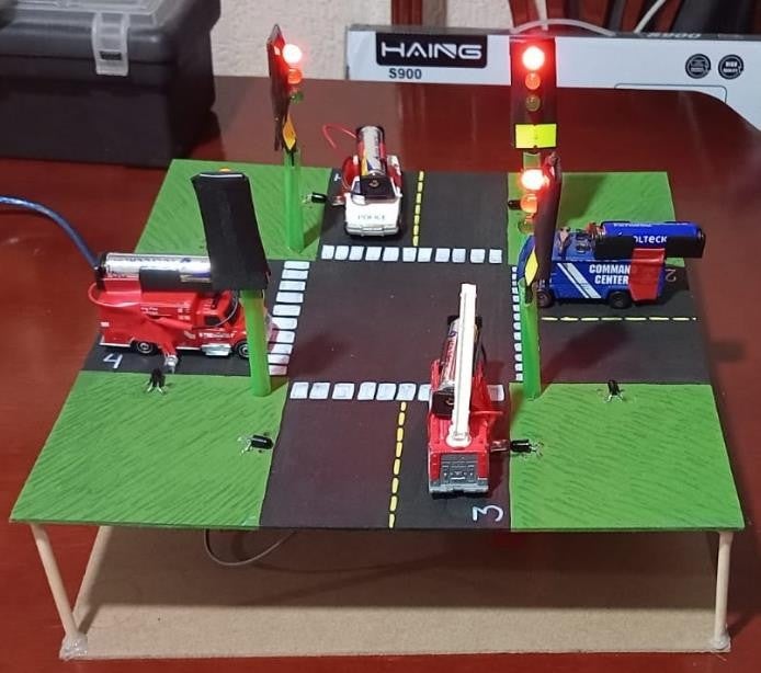
- Arduino Mega 2560.
- 4 mini-Traffic Light GYR modules.
- 8 receiver phototransistors.
- 4 infrared diodes.
- 4 battery holders type AA.
- A Model of a four-way street.
In the next images, the physical implementation can be seen:
Results
The intelligent traffic light system demonstrated its capability to enhance emergency vehicle response times in urban settings. By utilizing transmitters and receivers to detect emergency vehicles in specific lanes, the system dynamically adjusted traffic light timings, prioritizing green light extensions for lanes with detected emergencies.
This adaptive approach significantly improved the efficiency of emergency vehicle passage through intersections, potentially leading to faster response times and enhanced safety outcomes. The project highlighted the feasibility and advantages of integrating intelligent traffic management systems in urban environments, aiming to establish a new standard in urban mobility and safety by effectively balancing emergency vehicle prioritization with maintaining efficient traffic flow.
Feedback summary about MBD & SCADE
MBD (Model-Based Design) and SCADE are powerful tools for developing embedded systems. They streamline the design process by allowing for detailed modeling and simulation before physical prototyping. This approach helps catch potential issues early and improves overall system reliability. The structured nature of MBD and the capabilities of SCADE have made project development more efficient and collaborative, especially in complex applications.
SCADE, particularly, offers specialized tools and environments specifically designed for safety-critical applications, such as aerospace, automotive, and industrial control systems. Its graphical modeling capabilities and automatic code generation features not only streamline the design process but also ensure compliance with safety standards and regulations.
About the authors
Patricio Emiliano Morales Diaz Patricio Emiliano Morales Diaz, graduated as a technologist in software development from Centro de Enseñanza Técnica Industrial (CETI), Mexico in 2022. He is currently studying engineering in robotics at the Centro Universitario de Ciencias Exactas e Ingenierías (CUCEI). His interests include software development and programming, studies in embedded systems and the application of emerging technologies in innovative projects. Mariana Corona Aldana received the title of technologist in software development from Centro de Enseñanza Tecnica Industrial (CETI), México, in 2022. She is currently studying to get a degree in Robotics from Centro Universitario de Ciencias Exactas e Ingenierías (CUCEI). Her interests include development of both software and embedded software.
-


Introducing Ansys Electronics Desktop on Ansys Cloud
The Watch & Learn video article provides an overview of cloud computing from Electronics Desktop and details the product licenses and subscriptions to ANSYS Cloud Service that are...

How to Create a Reflector for a Center High-Mounted Stop Lamp (CHMSL)
This video article demonstrates how to create a reflector for a center high-mounted stop lamp. Optical Part design in Ansys SPEOS enables the design and validation of multiple...

Introducing the GEKO Turbulence Model in Ansys Fluent
The GEKO (GEneralized K-Omega) turbulence model offers a flexible, robust, general-purpose approach to RANS turbulence modeling. Introducing 2 videos: Part 1 provides background information on the model and a...

Postprocessing on Ansys EnSight
This video demonstrates exporting data from Fluent in EnSight Case Gold format, and it reviews the basic postprocessing capabilities of EnSight.

- Scade One – Bridging the Gap between Model-Based Design and Traditional Programming
- Scade One – An Open Model-Based Ecosystem, Ready for MBSE
- Scade One – A Visual Coding Experience
- How to Verify a Model on Host with SCADE Test? (Part 4 of 6)
- Using the SCADE Python APIs from your favorite IDE
- Introduction to the SCADE Environment (Part 1 of 5)
- How to integrate multiple SCADE models into one executable
- Scade One – Democratizing model-based development
- ARINC 661: the standard behind modern cockpit display systems
- How to Generate Code with SCADE Display (Part 6 of 6)

© 2025 Copyright ANSYS, Inc. All rights reserved.


