Tagged: AIm Tutorials, discovery-aim, structures
-
-
September 26, 2022 at 10:00 am
 FAQParticipant
This example is taken from Cornell University’s ANSYS AIM Learning Modules
Problem Specification
Consider the classic example of a circular hole in a rectangular plate of constant thickness. The plate is A514 steel with a modulus of elasticity of 29e6 psi and a Poisson ratio of 0.3. The thickness of the plate is 0.2 in., the diameter of the hole is 0.5 in., the length of the plate is 10 in. and the width of the plate 5 in., as the figure below indicates.

This tutorial will show you how to use ANSYS AIM to find the displacement and the stresses in the plate.
Pre-Analysis
Analytical vs. Numerical Approaches
We can either assume the geometry as an infinite plate and solve the problem analytically, or approximate the geometry as a collection of “finite elements”, and solve the problem numerically. The following flow chart compares the two approaches.
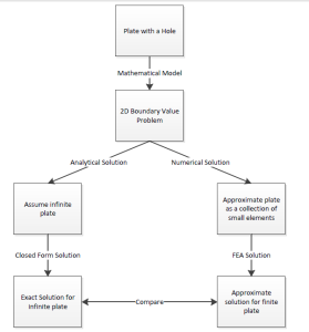
Let’s first review the analytical results for the infinite plate. We’ll then use these results to check the numerical solution from ANSYS.
Analytical Results
Displacement
Let’s estimate the expected displacement of the right edge relative to the center of the hole. We can get a reasonable estimate by neglecting the hole and approximating the entire plate as being in uniaxial tension. Dividing the applied tensile stress by the Young’s modulus gives the uniform strain in the x direction.

Multiplying this by the half-width (5 in) gives the expected displacement of the right edge as ~ 0.1724 in. We’ll check this against ANSYS AIM.
σr
Let’s consider the expected trends for σr, the radial stress, in the vicinity of the hole and far from the hole. The analytical solution for σr in an infinite plate is:

where a is the hole radius and σo is the applied uniform stress (denoted P in the problem specification). At the hole (r=a), this reduces to

This result can be understood by looking at a vanishingly small element at the hole as shown schematically below.
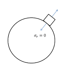
We see that σr at the hole is the normal stress at the hole. Since the hole is a free surface, this has to be zero.

Far from the hole, σr is a function of only. At = 0, σr ~ σo. This makes sense since r is aligned with x when = 0. At = 90 deg., σr ~ 0 which also makes sense since r is now aligned with y. We’ll check these trends in the ANSYS AIM results.
σ
Let’s next consider the expected trends for σ , the circumferential stress, in the vicinity of the hole and far from the hole. The analytical solution for σ in an infinite plate is:


At = 90 deg., σ = 3*σo for an infinite plate. This leads to a stress concentration factor of 3 for an infinite plate.

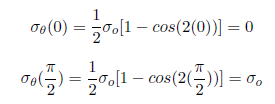
Far from the hole, σ is a function of only but its variation is the opposite of σr (which is not surprising since r and are orthogonal coordinates; when r is aligned with x, is aligned with y and vice-versa). As one goes around the hole from = 0 to = 90 deg., σ increases from 0 to σo. More trends to check in the ANSYS AIM results!
r
The analytical solution for the shear stress, r , in an infinite plate is:


By looking at a vanishingly small element at the hole, we see that r is the shear stress on a stress surface, so it has to be zero.
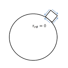

We can deduce that, far from the hole, r = 0 both at = 0 and = 90 deg. Even more trends to check in ANSYS AIM!
σx
First, let’s begin by finding the average stress, the nominal area stress, and the maximum stress with a concentration factor.

The concentration factor for an infinite plate with a hole is K = 3. The maximum stress for an infinite plate with a hole is:

Although there is no analytical solution for a finite plate with a hole, there is empirical data available to find a concentration factor. Using a Concentration Factor Chart (Cornell 3250 Students: See Figure 4.22 on page 158 in Deformable Bodies and Their Material Behavior), we find that d/w = 1 and thus K ~ 2.73. Now, we can find the maximum stress using the nominal stress and the concentration factor:

Geometry
Since the problem given to us represents a 2D state of stress, there are several simplifications that must be made due to the fact that Discovery AIM model will be 3D. Since the geometry is symmetric, when we draw the shape we want to create a one-quarter model. By taking advantage of symmetry, we can simplify the problem and also ensure that the model is not over constrained. Below video shows how to create the geometry.
Mesh
In this tutorial, we will be using Physics-Aware Meshing. Physics-aware meshing helps automate and simplify your problem setup. With physics-aware meshing, the computational mesh is generated automatically based on the solution fidelity setting and the physics inputs.
Physics Setup
In this video, you will learn how to define symmetric boundary conditions and pressure to the plate
Results Evaluation
In this video, you will evaluate stresses generated in the plate and its deformation
Verification
In the pre-analysis, the maximum stress was calculated. In order to verify that our simulation was accurate, a comparison must be made. From the Results Evaluation video, the maximum stress value can be determined.
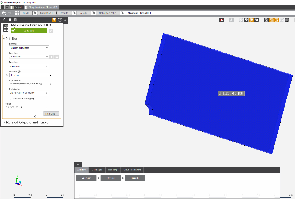
The table below compares the calculated and simulated values for maximum stress in the plate with a hole. With a difference of less than 5%, we can consider our simulation to be accurate. This small difference in results may be caused by not using enough mesh refinement.
Simulated Value Calculated Value Difference 3.1157E6 psi 3.033E6 psi 2.71%
-


Introducing Ansys Electronics Desktop on Ansys Cloud
The Watch & Learn video article provides an overview of cloud computing from Electronics Desktop and details the product licenses and subscriptions to ANSYS Cloud Service that are...

How to Create a Reflector for a Center High-Mounted Stop Lamp (CHMSL)
This video article demonstrates how to create a reflector for a center high-mounted stop lamp. Optical Part design in Ansys SPEOS enables the design and validation of multiple...

Introducing the GEKO Turbulence Model in Ansys Fluent
The GEKO (GEneralized K-Omega) turbulence model offers a flexible, robust, general-purpose approach to RANS turbulence modeling. Introducing 2 videos: Part 1 provides background information on the model and a...

Postprocessing on Ansys EnSight
This video demonstrates exporting data from Fluent in EnSight Case Gold format, and it reviews the basic postprocessing capabilities of EnSight.

- Discovery Live: How to change units
- Discovery AIM tutorial – Analysis of cantilever beam with I cross-section
- Discovery AIM – Scaling deformation contour results
- Discovery AIM tutorial – Structural Analysis of Plate with Hole
- How to setup a Parameter Study
- Creating a Helical Geometry in SpaceClaim
- Discovery SpaceClaim: Getting Started Tutorials
- Discovery AIM tutorial – 3D Finite-Element Analysis of a Bike Crank
- Convert 2D Drawings to 3D Models in Minutes with SpaceClaim
- FAQ: Missing Areas of the User Interface in Discovery Live

© 2026 Copyright ANSYS, Inc. All rights reserved.


