Are there integration points for the PIPE59 element, and, if so, where are they located? The Elements Manual states that the wave amplitude, ETA, is calculated at the integration points. The Theory Manual states that there are no integration points for the stiffness and mass matrices, but there are two integration points for the hydrodynamic loads. Are there integration points for the PIPE59 element, and, if so, where are they located?
-
-
March 17, 2023 at 9:00 am
FAQ
ParticipantFor most elements, integration points are used to perform the numerical integration necessary to form the various matrices. For some elements, like most beam and pipe elements, we know the closed form of the integration and the matrices are calculated directly from that. PIPE59 falls into this category and the stiffness and mass matrices are created directly in a manner similar to BEAM4. Some line elements, like BEAM189, require numerical integration to create the stiffness and mass matrices and BEAM189 has 3 integration points along its length. We need the integration points for PIPE59 to calculate the hydrodynamic loads from the WATER Table since the form of the hydrodynamic loads is unknown a priori. Chapter 13 of the Theory Reference describes the integration points for the various elements currently in use; however, PIPE59 is a legacy element, and its documentation is contained in Element Reference > Legacy Elements. For line elements such as the PIPE59 element, the possibility exists for 1, 2 or 3 integration points. PIPE59 has 2 integration points as it relates to the hydrodynamic effects and these are located at X = +/- 0.57735… This is measured in the element’s natural coordinate system that varies from X = -1 to X = +1. So, if the element was 10 units long, the integration points would be located at (1-.57735)*5 = 2.11325 and 1.57735*5 = 7.88675. NOTE: PIPE59 is a legacy element. Although this legacy element is available for use in your analysis, ANSYS, Inc. recommends using a current-technology element such as PIPE288 with KEYOPT(3) = 2, along with the appropriate ocean commands (OCxxxxxx).
-

Introducing Ansys Electronics Desktop on Ansys Cloud
The Watch & Learn video article provides an overview of cloud computing from Electronics Desktop and details the product licenses and subscriptions to ANSYS Cloud Service that are...

How to Create a Reflector for a Center High-Mounted Stop Lamp (CHMSL)
This video article demonstrates how to create a reflector for a center high-mounted stop lamp. Optical Part design in Ansys SPEOS enables the design and validation of multiple...

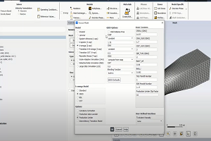
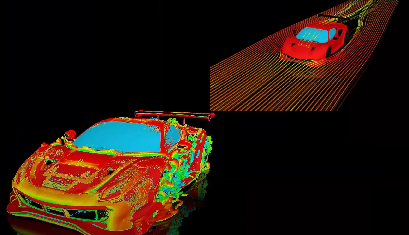
Introducing the GEKO Turbulence Model in Ansys Fluent
The GEKO (GEneralized K-Omega) turbulence model offers a flexible, robust, general-purpose approach to RANS turbulence modeling. Introducing 2 videos: Part 1Â provides background information on the model and a...

Postprocessing on Ansys EnSight
This video demonstrates exporting data from Fluent in EnSight Case Gold format, and it reviews the basic postprocessing capabilities of EnSight.
- ANSYS Mechanical: Node Merge
- ANSYS Mechanical: Node Move
- How to use ANSYS Workbench Meshing Virtual Topology
- Is there a way to show the element coordinate systems so that I know what direction the bending moments are in?
- How can we apply different loading conditions on both the top and bottom of a shell/surface body, e.g., temperature on top face and convection on bottom face.
- I am getting an error that mixed order mesh elements are not supported. How to overcome this issue?
- What is the difference between shell 63 and shell 181?
- Structural modeling with ANSYS Workbench Mechanical
- How to use ANSYS Workbench for Merging Mesh Nodes
- What might cause the “Error: HResult E_Fail has been returned from a call to a COM component” in SpaceClaim?
© 2025 Copyright ANSYS, Inc. All rights reserved.