

-
-
February 12, 2025 at 8:33 am
 SolutionParticipant

Photo credit: Jerry Wang @ PexelsThis article is part of a DO-178C blog series. It gives an overview of the DO-178C avionics software standard and details the process of developing, then verifying, safe compliant applications. You can find links to each part below:
- Part 1 (this blog): An introduction to DO-178C
- Part 2: Efficient Development of Safe Avionics Software with DO-178C Objectives Using SCADE Suite
- Part 3: Efficient Verification of Safe Avionics Software with DO-178C Objectives Using SCADE Suite
This article introduces DO-178C, officially titled “Software Considerations in Airborne Systems and Equipment Certification”. It is a key document in the aeronautic industry, providing guidelines for the development of safety-critical airborne software. It is jointly published by RTCA, Inc. (Radio Technical Commission for Aeronautics), and EUROCAE (European Organization for Civil Aviation Equipment) as ED-12C.
Development of Safety-Critical Airborne Software
Certification authorities require the aeronautics industry to demonstrate compliance with the applicable aeronautic regulations. Certification authorities recognize some safety standards (like DO-178C for safety-critical software used in commercial aircraft) as a means of compliance with the aeronautic regulations.
Published in 2011 by RTCA, Inc., in collaboration with EUROCAE, DO-178C (ED-12C) provides guidance for both airborne equipment developers and certification authorities. Rather than prescribing specific methodologies, it defines objectives to ensure that software performs its intended function with the level of safety confidence required for airworthiness compliance.
The standard guidance specifies:
- Objectives for software life-cycle processes.
- Description of activities and design considerations for achieving those objectives.
- Description of the evidence indicating that the objectives have been satisfied.
Relationship between ARP4754B, ARP4761A, and DO-178C
ARP4754B (ED-79B) and its companion ARP4761A (ED-135) are standards, published by SAE International in collaboration with EUROCAE. ARP4754B and DO-178C provide complementary guidance:
- ARP4754B provides guidance for system life-cycle processes.
- DO-178C provides guidance for software life-cycle processes.
The information flow between the system and software processes is summarized in the following figure.

Figure 1: Relation between ARP4754B and DO-178C processesDevelopment Assurance Levels
ARP4754B defines guidelines for the assignment of so-called “Development Assurance Levels” (DAL) to the system, to its components, and to software, regarding the most severe failure condition of the corresponding part.
ARP4754B defines a DAL for each item and allocates a Software Level to each software component as summarized below.
Level
Effect of anomalous behavior
A
Catastrophic failure condition for the aircraft
e.g., aircraft crashB
Hazardous/severe failure condition for the aircraft
e.g., several persons could be injuredC
Major failure condition for the aircraft
e.g., flight management system could be down, the pilot would have to do it manuallyD
Minor failure condition for the aircraft
e.g., some pilot-ground communications could have to be done manuallyE
No effect on aircraft operation or pilot workload
e.g., entertainment features may be downDO-178C documents structure
The DO-178C Standard is composed of a core document and a set of supplements as illustrated in the following figure.

Figure 2: structure of DO-178C documentsDO-178C serves as the foundational document for airborne software development. It outlines common objectives and activities for each process involved in producing such software. The core document is supplemented by additional guidelines tailored to specific techniques used in software development:
- DO-331 “Model-based Development and Verification Supplement” supplements the guidance given in DO-178C (core document) for the software components developed with model-based techniques.
- DO-332 “Object-Oriented Technology and Related Techniques Supplement” is applicable when object-oriented technology or related techniques are used as part of the software development life cycle.
- DO-333 “Formal Methods Supplement” is applicable in conjunction with DO-178C when Formal Methods are used as part of the software life cycle. Formal methods are mathematically-based techniques for the specification, development and verification of software aspects of systems.
Each supplement has the same structure as the core document (i.e., section titles are the same). For any unchanged section, the supplement explicitly states there is no change and does not repeat the core document.
On the other side, each supplement identifies the additions, modifications, and substitutions to DO-178C for a given technique:
- New and/or revised activities, explanatory text and software life cycle data are highlighted in the body of the supplement within existing sections or dedicated new sections.
- New and/or revised objectives are displayed in Annex A of the supplement.
Two other documents can also be considered in the context of DO-178C:
- DO-330 “Software Tools Qualification Considerations”: this standalone document (it is not considered as a supplement to DO-178C) defines the Tool Qualification Processes for both tool users and tool developers. It is interesting to note that the DO-330 document, as a standalone document, enables and encourages the use of this guidance outside the airborne software domain.
- DO-248C “Supporting Information for DO-178C” addresses the questions of the industry and regulatory authorities. It contains frequently asked questions (FAQs), discussion papers (DPs), and rationale.
Objective-oriented approach
The approach of DO-178C is based on the formulation of appropriate objectives and on the verification that these objectives are achieved. The DO-178C authors acknowledged that objectives are more essential and stable than specific procedures. The ways of achieving an objective may vary between companies, and they may vary over time with the evolution of methods, techniques, and tools. DO-178C never states that one should use design method X, coding rules Y, or tool Z. DO-178C does not even impose a specific life cycle.
The general approach is the following:
- Ensure appropriate goals are defined. For instance: a) Software level and b) Design standards.
- Define procedures for the verification of these goals. For instance: a) Verify that independence of activities matches the software level, b) Verify that design standards are met and that the design is complete, accurate, and traceable.
- Define procedures for verifying that the above-mentioned verification activities have been performed satisfactorily. For instance: a) Review of requirements-based test cases and procedures is achieved, b) Coverage of requirements by testing is achieved.
DO-178C processes overview
DO-178C structures activities as a hierarchy of “processes”, as illustrated in Figure 3. DO-178C defines three top-level groups of processes:
- The software planning process defines and coordinates the activities of the software development and integral processes for a project.
- The software development processes produce the software product.
- The integral processes ensure the correctness, control, and confidence of the software life-cycle processes and their outputs. The integral processes are the software verification process, the software configuration management process, the software quality assurance process, and the certification liaison process. The integral processes are performed concurrently with the software development processes and the planning process throughout the software life cycle.

Figure 3: DO-178C structure of lifecycle processesIn the remainder of this blog, we will focus on the development and verification processes.
DO-178C Development Processes
The software development processes, as illustrated below, are composed of:
- The software requirements process, which produces the high-level requirements (HLRs).
- The software design process, which produces the low-level requirements (LLRs) and the software architecture through one or more refinements of the HLRs.
- The software coding process, which produces the source code and object code.
- The integration process, which produces executable object code and builds up to the integrated system or equipment.

Figure 4: DO-178C development processesThe HLRs are produced directly through analysis of system requirements and system architecture and their allocation to software. They include specifications of functional and operational requirements, timing and memory constraints, hardware and software interfaces, failure detection and safety monitoring requirements, as well as partitioning requirements.
The HLRs are further developed during the software design process, thus producing the software architecture and the LLRs. These include descriptions of the input/output, the data and control flow, resource limitations, scheduling and communication mechanisms, as well as software components.
Through the coding process, the LLRs are implemented as source code.
The source code is compiled and linked by the integration process into an executable code loaded on the target environment.
At all stages of the development process, traceability is required: between system requirements and HLRs; between HLRs and LLRs; between LLRs and source code; and also between requirements and tests.
DO-178C Verification Processes
The purpose of the software verification processes is “to detect and report errors that may have been introduced during the software development processes.”
Testing is part of the verification processes, but verification is not just testing: the verification processes also rely on reviews and analyses. Reviews are qualitative, whereas analyses are more detailed and should be reproducible (e.g., compliance with coding standards).
Verification activities cover all the processes, from the planning process to the development processes; there are also verifications of the verification activities.
Reviews and analyses of HLRs
The objective of reviews and analyses is to confirm that the HLRs satisfy the following:
- Compliance with system requirements
- Accuracy and consistency: each HLR is accurate, unambiguous and sufficiently detailed; requirements do not conflict with each other
- Compatibility with target computer
- Verifiability
- Compliance with standards as defined by the planning process
- Traceability with system requirements
- Algorithm accuracy
Reviews and analyses of LLRs and architecture
The objective of these reviews and analyses is to detect and report errors possibly introduced during the software design process. These reviews and analyses confirm that the software LLRs and architecture satisfy the following:
- Compliance with high-level requirements: the software LLRs satisfy the software HLRs
- Accuracy and consistency
- Compatibility with target computer: no conflicts exist between the software requirements and the hardware/software features of the target computer, especially the use of resources (e.g., bus loading), system response times, and input/output hardware
- Verifiability: each LLR can be verified
- Compliance with Software Design Standards as defined by the software planning process
- Traceability: the objective is to ensure that all HLRs were considered in the development of the LLRs
- Algorithm aspects: ensure the accuracy and behavior of the proposed algorithms, especially in discontinuities (e.g., mode changes, crossing value boundaries)
- The Software Architecture is compatible with the HLRs, is consistent and compatible with the target computer, is verifiable, and conforms to standards
- Software partitioning integrity is confirmed
Reviews and analyses of the source code
The objective is to detect and report errors that may have been introduced during the software coding process. These reviews and analyses confirm that the outputs of the software coding process are accurate, complete, and can be verified. Primary concerns include correctness of the code with respect to the LLRs and the software architecture, and compliance with the Software Code Standards.
Software testing process
Testing has two complementary objectives. One objective is to demonstrate that the software satisfies its requirements. The second objective is to demonstrate, with a high degree of confidence, that all errors which could lead to unacceptable failure conditions as determined by the system safety assessment process, have been removed.
There are three types of testing activities:
- Low-level testing: to verify that each software component complies with its LLRs
- Software integration testing: to verify the interrelationships between software requirements and components and to verify the implementation of the software requirements and software components within the software architecture
- Hardware/software integration testing: to verify correct operation of the software in the target computer environment
As shown in the following figure, DO-178C dictates that all test cases be requirements-based. When it is not possible to verify specific software requirements by exercising the software in a realistic test environment, other means and their justification shall be provided according to DO-178C, §6.2b.

Figure 5: DO-178C testing processTest coverage analysis
Test coverage analysis is a two-step activity:
- Requirements-based test coverage analysis determines how well the requirement-based testing covered the software requirements. The main purpose of this step is to verify that all requirements have been implemented. Requirements-based Test coverage analysis shall be considered for both HLRs and LLRs
- Structural coverage analysis determines which code structures, including interfaces between components, are exercised by requirements-based test procedures. Its purposes are:
- Ensures all code structures, including interfaces, were executed at least once
- Detects untested functions which could be unintentional
- Identifies extraneous code, including dead code
- Helps to confirm if deactivated code is truly deactivated
- Serves as completion criteria for testing efforts
The structural coverage criteria that must be achieved depend on the software level:
- Level A: MC/DC (Modified Condition / Decision Coverage) is required
- Level B: Decision Coverage is required,
- Level C: Statement Coverage is required.
Structural coverage resolution
If structural coverage analysis reveals code structures including interfaces that were not exercised, resolution is required:
- If it is due to shortcomings in the test cases, then test cases should be supplemented or test procedures changed.
- If it is due to inadequacies in the requirements, then the requirements must be changed and test cases developed and executed.
- If it is extraneous code, including dead code (i.e., it is not traceable to any system or software requirement and its presence is an error), then this code should be removed.
- If it is deactivated code (it cannot be executed, but its presence is not an error):
- If it is not intended to be executed in any configuration, then analysis and testing should show that the means by which such code could be inadvertently executed are prevented, isolated, or eliminated.
- If it is only executed in certain configurations, the operational configuration for execution of this code should be established and additional test cases should be developed to satisfy coverage objectives.
DO-331 Model-Based Development and Verification Processes
Model-based techniques are more and more used in the design of safety critical software components because they are considered as a very efficient approach to develop complex software while increasing productivity. The DO-331 supplement, in conjunction with the DO-178C core document, is applicable when model-based techniques are used for the development and verification of a given software component.
Model Definition
According to the DO-331 glossary, a model is “an abstract representation of a given set of aspects of a system that is used for analysis, verification, simulation, code generation, or any combination thereof. A model should be unambiguous, regardless of its level of abstraction.”
DO-331, MB.1.0 addresses model(s) that have the following characteristics:
- “The model is completely described using an explicitly identified modeling notation. The modeling notation may be graphical and/or textual.
- The model contains software requirements and/or software architecture definition.
- The model is of a form and type that is used for direct analysis or behavioral evaluation as supported by the software development process or the software verification process.”
There is a large diversity of modeling notations that differ significantly regarding for instance the following aspects:
- The modeling notations range from non-formal (e.g., UML, SysML) to formal (e.g., Scade, B)
- They may be based on various concepts and representations such as data flow, state machines, sequence charts
- They may be synchronous (e.g., Scade) or asynchronous (e.g., UML)
Model Categorization
DO-331, MB.1.6.2 defines two types of models: specification model and design model.
A Specification Model represents “high-level requirements that provide an abstract representation of functional performance, interface, or safety characteristics of software components“. It supports an understanding of software functionality and does not prescribe a specific software implementation or architecture.
A Design Model defines “any software design such as low-level requirements, software architecture, algorithms, component internal data structures, data flow and/or control flow.” It describes the internal details of a given software component.
Moreover, two important properties are attached to the concept of model:
- A model cannot be categorized as both specification model and design model.
- Whatever the model (specification or design), there must be requirements above the model. They should be external to the model and should be a complete set of requirements and constraints
Impact of Model-Based Development on DO-178C Development Processes
DO-331 Table MB.1-1 provides examples of Model usage in the context of industrial projects that illustrate different strategies for Model-Based Development (MBD).
In the context of “MB Example 1” of Table MB.1-1, the DO-178C traditional development process such as described earlier can significantly be improved as follows:
- Software requirements are usually textual requirements supplemented by pictures, when appropriate, that are derived from System Requirement Allocated to Software (SRATS)
- A design model is developed for LLRs and Architecture
- Source code is developed with the support of an automatic code generator
Impact of Model-Based Development on DO-178C Verification Processes
Various verification techniques are available when using model-based development. Model Simulation can be considered as one of the most efficient.
DO-331 provides a precise definition and some specific guidance in §MB.6.8: Model Simulation is defined as “The activity of exercising the behavior of a model using a model simulator“. In this context, the model simulator may or may not be executing code representative of the target code. Simulation is different from testing which is the execution of the “real” Executable Object Code (EOC) on target.
Model Simulation supports the verification of objectives of DO-331, Table MB.A-4, like:
- Compliance with HLRs for models containing LLRs
- Accuracy and consistency verifiability
- Algorithm aspects
On the other hand, Model Simulation cannot be used to satisfy objectives such as compatibility with the target computer, conformance to standards, traceability or partitioning integrity. Reviews and analyses are then required to complete model verification.
If Model Simulation is used for verification to satisfy a DO-178C objective, the model simulator shall be qualified as a verification tool and new DO-331 objectives shall be considered during the verification of the software LLRs. In particular, the following objectives are considered in addition to the existing objectives:
- “Simulation cases are correct” (Table MB.A-4 objective MB14)
- “Simulation procedures are correct” (Table MB.A-4 objective MB15)
- “Simulation results are correct and discrepancies explained” (Table MB.A-4 objective MB16)
Model coverage analysis for design models
Model coverage analysis concerns the “design models” (as opposed to “specification models”). Model coverage analysis determines which requirements expressed by the design model were not exercised by verification based on the requirements from which the design model was developed. This analysis may assist in finding unintended functionality in the design model.
Model coverage analysis is different from structural coverage analysis. Both model coverage and structural code coverage shall be achieved to satisfy objectives of DO-331 Table MB.A-7. As stated in DO-331 FAQ-11, the implication of model level coverage to the generated code level allows to satisfy structural code coverage objectives.
DO-331 objective MB.A-7#4 identifies model coverage (§6.7) as a supporting activity for assessing coverage of the low-level requirements contained in a design model. Moreover, as stated in DO-331 MB.6.7.2, model coverage analysis contributes to the detection and resolution of:
- Shortcomings in requirements-based verification cases or procedures
- Inadequacies or shortcomings in requirements from which the design model was developed
- Derived requirements expressed by the model
- Deactivated functionality expressed by the design model
- Unintended functionality expressed by the design model
Model coverage criteria
Even if it is not possible to impose specific detailed model coverage criteria due to various modeling notations, DO-331 Table MB.6-1 provides an example of criteria that are relevant to assess model coverage according to the objectives defined in DO-178C, see §6.4.2.1 and §6.4.2.2.
General principles such as coverage of all characteristics of the functionality, coverage of equivalence classes and boundary/singular values for numeric data, and coverage of all derived requirements are highlighted in the example from DO-331, Table MB.6-1.
The applicant may use any alternative coverage criteria provided these criteria comply with the objectives defined in DO-178C, see § 6.4.2.1 and §6.4.2.2. These criteria should be defined in the Software Verification Plan of the applicant.
Stay tuned
In this blog, we’ve introduced DO-178C, the primary document by which the certification authorities approve all commercial software-based aircraft systems.
An upcoming blog series will showcase how SCADE enables model-based development, allowing engineers to satisfy DO-178C and DO-331 objectives for development and verification.
If you’d like to learn more about Ansys SCADE Solutions, we’d love to hear from you! Get in touch on our product page.
About the author

Gunther Siegel (LinkedIn) leads the Embedded Software product line within Ansys. In this role, he acts as the primary technical interface with strategic customers and partners, driving collaboration and innovation. Mr. Siegel brings over 15 years of expertise in technical leadership, product development and strategic business growth.
-


Introducing Ansys Electronics Desktop on Ansys Cloud
The Watch & Learn video article provides an overview of cloud computing from Electronics Desktop and details the product licenses and subscriptions to ANSYS Cloud Service that are...
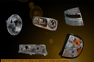
How to Create a Reflector for a Center High-Mounted Stop Lamp (CHMSL)
This video article demonstrates how to create a reflector for a center high-mounted stop lamp. Optical Part design in Ansys SPEOS enables the design and validation of multiple...
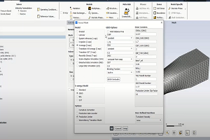
Introducing the GEKO Turbulence Model in Ansys Fluent
The GEKO (GEneralized K-Omega) turbulence model offers a flexible, robust, general-purpose approach to RANS turbulence modeling. Introducing 2 videos: Part 1 provides background information on the model and a...
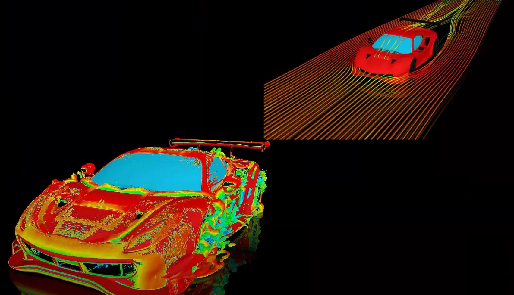
Postprocessing on Ansys EnSight
This video demonstrates exporting data from Fluent in EnSight Case Gold format, and it reviews the basic postprocessing capabilities of EnSight.

- An introduction to DO-178C
- ARINC 661: the standard behind modern cockpit display systems
- Scade One – Bridging the Gap between Model-Based Design and Traditional Programming
- Scade One – An Open Model-Based Ecosystem, Ready for MBSE
- Scade One – A Visual Coding Experience
- Using the SCADE Python APIs from your favorite IDE
- SCADE and STK – Satellite Attitude Control
- How to integrate multiple SCADE models into one executable
- Introduction to Formal Verification and SCADE Suite Design Verifier
- Scade One – Democratizing model-based development

© 2026 Copyright ANSYS, Inc. All rights reserved.
