Tagged: cinvestav, guest article, SCADE, scade suite, scade test, student
-
-
October 15, 2024 at 5:06 pm
 SolutionParticipant
Guest Article – Student – Aerogenerator Rotor Blade Angle Control System with SCADE
This article is a guest contribution from Cinvestav. It was written by a student group as part of Masters-level, semester long SCADE academic program course.
It explains the design and simulation of a system that controls the optimal inclination of rotor blades in the aerogenerator component of a wind turbine.
If you are an academic and are interested in teaching an engineering curriculum backed by Ansys tools, please have a look at our Ansys Funded Curriculum page.
Introduction
Wind turbine systems convert the kinetic energy of the wind into electrical energy. A wind turbine system is comprised of several essential and critical components, which work together to optimize the energy generated. One of the most critical systems of a wind turbine is the Rotor Blade Angle Control, which refers to a set of components and software designed to control the orientation of the blades.
The Rotor Blade Angle Control System refers to a set of components and software designed to control the orientation of the blades and its main advantages is the optimization of the generated energy, the automatic adjustment of the blade angle maximizes the use of the wind energy, also allows to adapt to changes in wind speed. Additional it provides protection of the wind turbine, preventing wind turbine working outside of its safe limits.
This project consists of a basic Rotor Blade Angle Control System for wind turbines and was designed using ANSYS SCADE software. The design implementation begins with mapping the Mathematical and Physical models used in literature for blade angle control, with operators ANSYS SCADE to calculate the angle of the blades according to the input wind speed, among other parameters that for this work were established statically. Also, operators were implemented to monitor the system. The system is capable of continuously monitoring the wind speed and calculating the optimal degree of the blades. The system will allow knowing at all times the wind speed and PM (generation power) in real time. The system will have a module for the generation of warnings, which will allow monitoring the behavior of the wind speed in order to implement mechanisms to prevent mechanical damage to the wind turbine.
As a result, the proposed design was implemented using the ARDUINO system in simulation. This simulation environment allows working with the Rotor Blade Angle Control System design code generated by the ANSYS SCADE tool, without having any problem at the time of implementation, which indicates that the generated code helps to speed up the implementation process and ensures consistency between the conceptual design and the practical implementation.
Model Of Wind Turbine Behavior
Figure 1 shows gray color the range operation pitch control for this implementation, it can be seen that after a speed of 11.5 m/s (cut-in) the power generated by the wind turbine is maximum and when exceeds 25 m/s (cut-on) the wind turbine is shutdown to prevent mechanical damages.
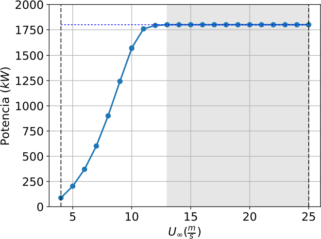
Figure 1 – Optimal operation of the aerogenerator for power generationDue to the objective project, only the wind speed is being considered to modify the blade angle. In the literature information was found on the relationship between wind speed m/s and blade angle for this operation region seen above. Bellow in table 1 is detailed wind speed versus pitch angle [1]:
Wind speed (m/s)
Angle $$\beta$$ (°)
11.5
0.769
12
2.21
12.1
2.53
12.2
2.94
12.3
3.43
12.4
3.98
12.5
4.55
13
7.3495
14
12.0014
15
15.6949
16
18.7385
17
21.309
Table 1 – Relationship between wind speed and optimum blade angle [1]
With this information we can generate a polynomial function of degree two to find the best Beta for the input wind speed value, having as a result the following equation after adjustment of the data (see Figure 2):
$$\beta = -0.1597 * v^{2}_{wind} + 8.183 * v_{wind} – 72.212$$
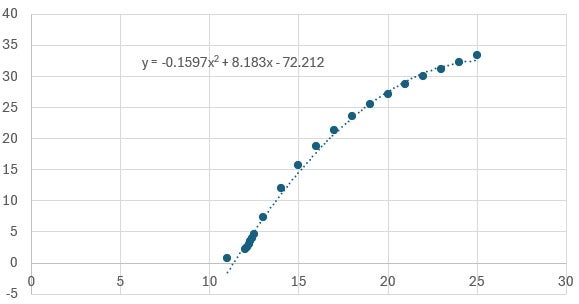
Figure 2 – Polynomial fit to Table 1 dataAs part of the monitoring, the following equation was used to calculate the PM for 3m/s to 25 m/s range, according to the calculated Beta value [2][3]:
$$P_{m} = C_{p}(\lambda, \beta)^{\rho A}_{2}v^{3}_{wind}$$
Where:
Variable
Description
$$P_{m}$$
Mechanical output power of the turbine (W)
$$cp$$
Performance coefficient of the turbine
$$\rho$$
Air density (kg/m3)
$$A$$
Turbine swept area (m2)
$$v_{wind}$$
Wind speed (m/s)
$$\lambda$$
Tip speed ratio of the rotor blade tip speed to wind speed
$$\beta$$
Blade pitch angle (deg)
Coefficients
C1 = 0.5176, C2 = 116, C3 = 0.4, C4 = 5, C5 = 21 and C6 = 0.0068
Table 2 – Variables involved in the correct operation of an aerogenerator
A generic equation is used to model 𝐶𝑃(𝜆, 𝛽). This equation, based on the modeling turbine characteristics, is:
$$C_{p}(\lambda, \beta) = C_{1}(\frac{C_{2}}{\lambda_{i}}- C_{3}\beta – C_{4})e^{-\frac{C_{5}}{\lambda_{i}}}+C_{i}\lambda$$
Where:
$$\frac{1}{\lambda_{i}}=\frac{1}{\lambda+0.08\beta}-\frac{0.035}{\beta^{3}+1}$$
Stage definitions
This project was developed in two stages begin with the definition of Primary and Final control elements and following with the law of control and related algorithms. Below in Table 3 appears a brief description of above.
Pitch control stages:
Stage
Definition
Description
1
Primary control elements:
-Wind Speed Sensors
-Blade orientation sensor
-Turbine Speed sensor
These sensors measure wind speed and direction in real time. Wind speed is crucial because it determines the force with which the wind hits the rotor blades and, therefore, the amount of energy that can be captured.
1
Final control elements:
-Servomotors (Actuators)
These are the mechanical devices responsible for modifying the angle of the blades according to the instructions of the automatic control system. These actuators must be accurate and fast to ensure an adequate response to changes in wind conditions.
2
Law of control
Typical PID algorithm from scratch.
2
Set Point Algorithm
Automatic Control System
Based on the information provided by the sensors, the automatic control system calculates the optimum angle of the rotor blades at all times. This calculation takes into account wind speed, wind direction and other environmental parameters to adjust the blade angle and optimize energy efficiency.
Table 3 – The different stages of step control
Design in SCADE
Below are some of the requirements implemented:
Rotor Blade Angle Control System behavior
RBAC_HLR_ RBACB_01
When the wind speed is less than 11.5 m/s, the RBAC shall be Off. The output of angle should be set to 0.RBAC_HLR_ RBACB_02
The RBAC shall be set on when the wind speed is greater than 11.5 m/sRBAC_HLR_ RBACB_03
The RBAC shall automatically go off when the wind speed is greater than 25.5 m/s. The output of angle should be set to the last RBAC output value.RBAC_HLR_ RBACB_04
If the wind speed is within the ranges 11.5 m/s-25 m/s, the RBAC shall be on and regulate the blade angle. The alarm (statusSystemOperation) shall be set to TRUE.RBAC_HLR_ RBACB_05
If the wind speed is greater than 25 m/s, the RBAC shall be on and regulate the blade angle. The alarm(statusSystem) shall be set to TRUE.RBAC_HLR_ RBACB_0C
The RBAC system shall be automatically disabled when the wind speed Is less than 11.5. The output Output1, Output2, Output3 shall be set to 0.RBAC _HLR_ RBACB_07
The RBAC system shall be automatically disabled when the wind speed Is greater than 25m/s. The output Output1, Output2, Output3 shall be set to 100.Blade adjusting control
RBAC_HLR_BAC_01
When the RBAC is off and the alarm(statusSystemOperation) is FALSE, the blades angle shall be adjust using 0 degrees.RBAC_HLR_BAC_02
When the RBAC is off and the alarm (statusSystemOperation) is TRUE, the blades angle shall be adjust using the max angle (100%).RBAC_HLR_ BAC _03
When the RBAC is on, the blade angle shall be automatically adjusted.RBAC_HLR_BAC _04
The regulation shall be done using a PID controller (proportional, integral and derivative algorithm), with P_, I_ and D_ factors.Blade angle management
RBAC_HLR_BAM_01
The blade angle shall be managed only when the RBAC is enabled.RBAC_HLR_BAM_02
The blade angle shall be set to the angle calculated using the current wind speed automatically.RBAC_HLR_BAM_03
The blade angle shall be increased when the wind speed increase.RBAC_HLR_BAM_04
The blade angle shall be decreased when the wind speed decrease.Model
BLOCK: Aerogenerator.
As part of the design of the rotor blade angle control system, the different operators make use of the constants shown in Table 5.
Name
Type
Value
Comments
Afloat3220106Area
C1float320.5176Constant 1
C2float32116Constant 2
C3float320Constant 3
C4float325Constant 4
C5float3221Constant 5
C6float320.0068Constant 6
cut_infloat324Pitch control on
cut_onfloat3225Shutdown
D_float320.1Differencial constant
I_float320.1Integral constant
lambdafloat320.5Relation speeds wind –
turbine
lower_limitfloat3212Warning
Pfloat321.23Proportional constant
P_float321.2Proportional constant
upper_limitfloat3225Alarm
Table 5 – Constants
VIEWS TOP DESIGN SCADE.
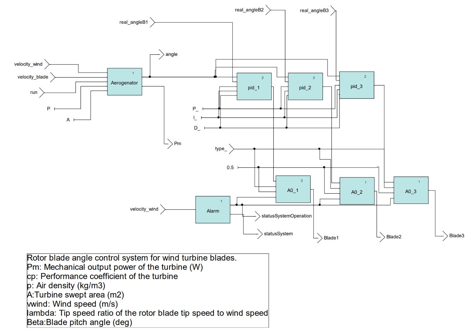
The Figure 3 shows the TOP project of the design made in SCADE. This top operator, the Wind Turbine operator is shown which receives the wind speed as input. Using the mathematical models described in the section “MODEL OF WIND TURBINE BEHAVIOR” the new angle (Beta) for the blades is calculated, and the expected power generated (PM) is also calculated by applying the values to place the blades at the new angle.
The PID operators for each of the blades are also shown, as well as the analog operators that allow the 3 wind turbine blades to be reoriented to the new angle. The alarm module is also observed, which allows us to know the status of the systems (green means that there is a lower wind speed for the operation of the system, yellow means that the system is operating with the safe limits of wind speed and red means that the system is operating in unsafe limits).
The following list shows the dependency tree of the model operators.
- beta
- mathext::PowerRR
- Top_Aerogenator
- A0_1
- A0_2
- A0_3
- Aerogenator
- Beta_c
- lambda
- pm
- CP
- lambda_i
- mathext::PowerRR
- Alarm
- pid_1
- pwlinear::LimiterUnSymmetrical [2]
- pid_2
- pwlinear::LimiterUnSymmetrical [2]
- pid_3
- pwlinear::LimiterUnSymmetrical [2]
- CP
Figure 4 below shows the view of the Aerogenerator_1. This operator makes use of 3 operators. The first
one is Beta_c (see Figure 5) which implements the equation
$$\beta = -0.1597 * v^{2}_{wind} + 8.183 * v_{wind} – 72.212$$
lambda_ is the operation of $$\frac{velocity\_wind}{velocity\_blade}$$ and the PM operator contains the mathematical models
$$C_{p}(\lambda, \beta) = C_{1}(\frac{C_{2}}{\lambda_{i}}- C_{3}\beta – C_{4})e^{-\frac{C_{5}}{\lambda_{i}}}+C_{i}\lambda$$
Where
$$\frac{1}{\lambda_{i}}=\frac{1}{\lambda+0.08\beta}-\frac{0.035}{\beta^{3}+1}$$
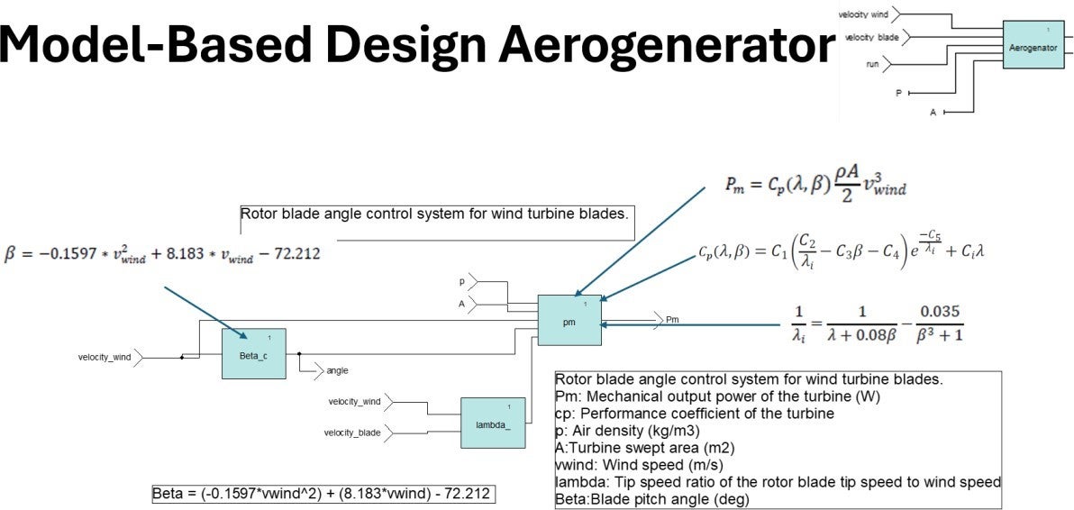
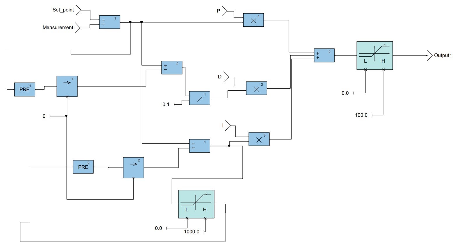
Figure 4 – Aerogenerator modelThe next Figure 6 shows the operator of PID.
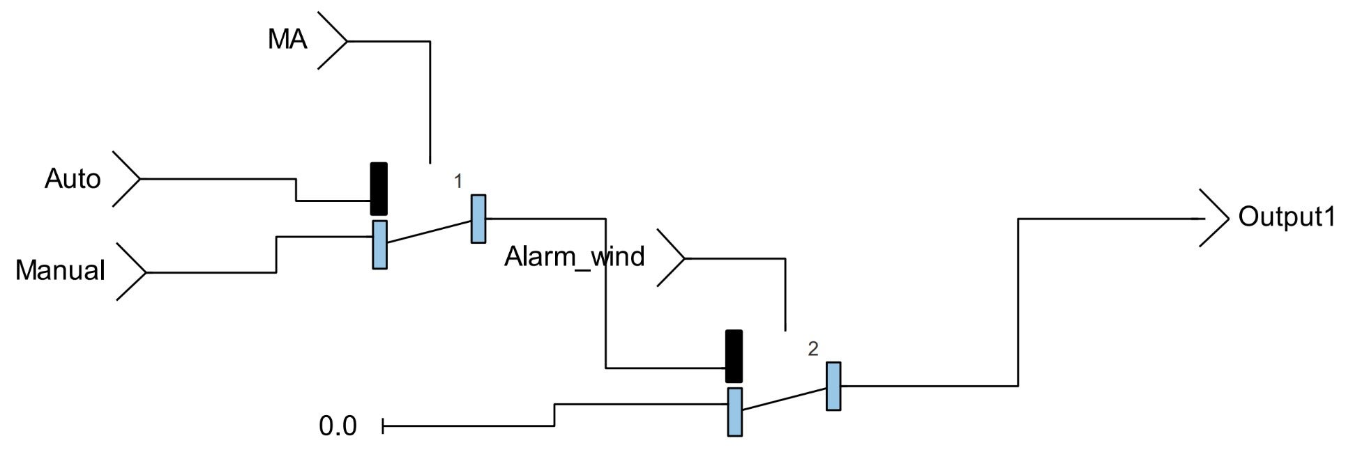
The next Figure 7 shows the operator of ANALOG Output.
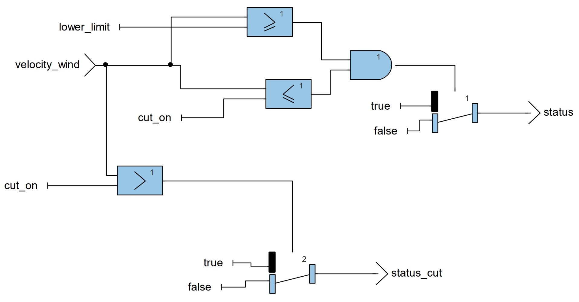
The next Figure 8 shows the operator of Alarm. The alarm module allows us to know the status of the systems (green means that there is a lower wind speed for the operation of the system, yellow means that the system is operating with the safe limits of wind speed and red means that the system is operating in unsafe limits).
Implementation
For validation and tests implementation, a free Arduino simulator was used [4]. In this scenario of virtual implementation, the project integration was successfully obtained from SCADE and compiled into ATMEGA microcontroller from Arduino UNO family (https://wokwi.com/projects/403062824550713345).
Figure 9 shows the design of the ROTOR BLADE ANGLE CONTROL SYSTEM implementation in the Arduino environment.
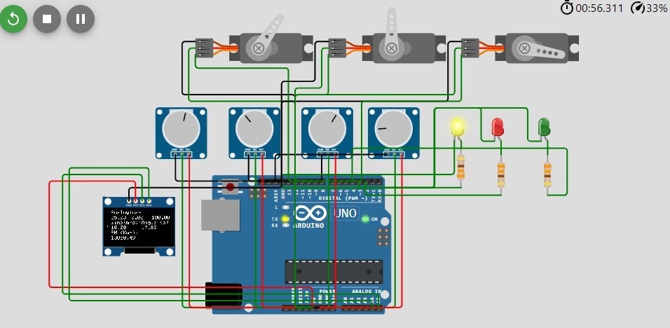
Figure 9 – Rotor blade angle control system in ArduinoThe following figures show the rotor blade angle control system in simulation mode, using the ANSYS SCADE STUDENT tool.
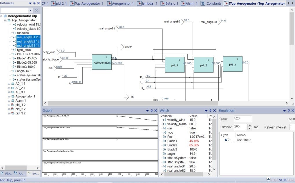
Figure 10 – Simulation 1 of the operation of the angle change and its regulation using the PIDs
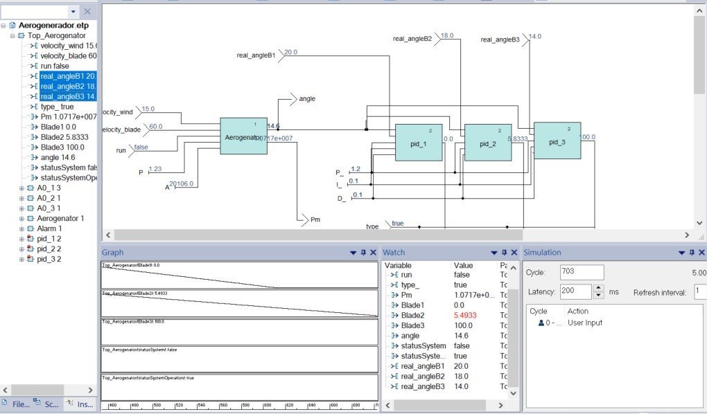
Figure 11 – Simulation 2 of the operation of the angle change and its regulation using the PIDs
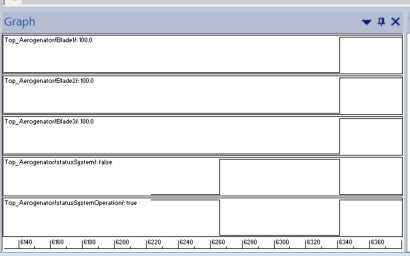
Figure 12 – Simulation 3 using the graph module to monitor the change of the pid outputs for blade angle adjustment, as well as the activation of alarmsResults
The RBACS system demonstrates the ability to calculate the optimum blade angle considering the wind speed and the application of different mathematical models. With the new angle, the system is able to automatically adjust the blade angle through 3 servomotors (1 servomotor per blade).
This proposed approach allows to improve the capabilities of a wind turbine in different aspects, for example, accurately control the angle of the blades, maximizing energy efficiency through dynamic and adaptive rotor blade angle control and implement robust functional safety measures to avoid risks of critical failures.
Conclusions
The ANSYS SCADE suite is a very powerful tool that enables critical software designs using a model- based approach. This work proposed a ROTOR BLADE ANGLE CONTROL SYSTEM and its monitoring, being a critical type of system for several reasons, i.e., achieving energy efficiency, adaptation to wind conditions, structural safety and performance optimization. Using the ANSYS SCADE tool allowed us to accomplish the objectives of this project easily and on time. Thanks to its intuitive and easy to understand interfaces. The code generated by the ANSYS SCADE tool is easy to interpret and portable, which allows us to implement it on any microcontroller that supports the GCC compiler. In this work the ARDUINO platform was used and there were no problems in implementing the code generated by this tool. Also, it was observed that the code generated by ANSYS SCADE can be integrated with C code made by a programmer. With the implementation of this project, we can conclude that the ANSYS SCADE tool allows an easy mapping of mathematical models.
References
[1] Zhou, F., C Liu, J. (2018). Pitch controller design of wind turbine based on nonlinear PI/PD control. Shock and Vibration, 2018(1), 7859510.
[2] Harish, V. S. K. V., C Sant, A. V. (2021). Grid integration of wind energy conversion systems. Alternative Energy Resources: The Way to a Sustainable Modern Society, 45-66.
[3] MATLAB. (Access July 11 2024). Wind Turbine. Mathworks. https://la.mathworks.com/help/sps/powersys/ref/windturbine.html
[4] WOKWI. (Access July 11 2024). Simulate IoT Projects in Your Browser. WOKWI. https://wokwi.com/
About the authors
Jaciel D. Hernandez-Resendiz received the PhD in Electrical and Electronic Engineering in the Unidad Académica Multidisciplinaria Reynosa-RODHE de la Universidad Autónoma de Tamaulipas, México. He received master’s degree in engineering from Polytechnic University of Victoria, Mexico in 2018, the B.Sc. degree in Information Technology from Polytechnic University of Victoria, Mexico in 2014. His research interests are Machine learning, Computer Vision, Information Retrieval and Process Mining.
Julio Cesar Garcia Mendez is a PhD student at CINVESTAV Tamaulipas, Mexico, He holds a bachelor’s degree in electronics, master’s degree in engineering and Diploma course about Wind Turbine Maintenance by Vestas. He has eleven years’ experience in Power Plant Generation (EDF, Falcon Group, Gas Natural) and ten years’ experience in Academics (Universidad Politécnica de Victoria).
- beta
-


Introducing Ansys Electronics Desktop on Ansys Cloud
The Watch & Learn video article provides an overview of cloud computing from Electronics Desktop and details the product licenses and subscriptions to ANSYS Cloud Service that are...

How to Create a Reflector for a Center High-Mounted Stop Lamp (CHMSL)
This video article demonstrates how to create a reflector for a center high-mounted stop lamp. Optical Part design in Ansys SPEOS enables the design and validation of multiple...

Introducing the GEKO Turbulence Model in Ansys Fluent
The GEKO (GEneralized K-Omega) turbulence model offers a flexible, robust, general-purpose approach to RANS turbulence modeling. Introducing 2 videos: Part 1 provides background information on the model and a...

Postprocessing on Ansys EnSight
This video demonstrates exporting data from Fluent in EnSight Case Gold format, and it reviews the basic postprocessing capabilities of EnSight.

- An introduction to DO-178C
- Scade One – Bridging the Gap between Model-Based Design and Traditional Programming
- ARINC 661: the standard behind modern cockpit display systems
- Scade One – An Open Model-Based Ecosystem, Ready for MBSE
- Scade One – A Visual Coding Experience
- Using the SCADE Python APIs from your favorite IDE
- How to Verify a Model on Host with SCADE Test? (Part 4 of 6)
- How to integrate multiple SCADE models into one executable
- Scade One – Democratizing model-based development
- Introduction to the SCADE Environment (Part 1 of 5)

© 2026 Copyright ANSYS, Inc. All rights reserved.


