Tagged: guest article, SCADE, scade suite, stabilization, student, UPB
-
-
November 15, 2024 at 10:31 am
 SolutionParticipant
Guest Article – Student – A Dive into the Development of Stabilization Platforms
This article is a guest contribution from University Politehnica of Bucharest. It was written by a PhD student as part of a research project.
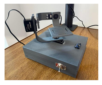
It explains the design, integration and testing of a self-stabilizing platform.
If you are an academic and are interested in teaching an engineering curriculum backed by Ansys tools, please have a look at our SCADE academic program course and Ansys Funded Curriculum page.
Introduction
In the realm of modern defense systems, the stabilization platform stands as a cornerstone. Imagine a high-tech system capable of maintaining a constant line of sight even amidst unpredictable conditions. This platform is vital for applications like aerial surveillance, satellite imagery, and advanced industrial measurements. It operates by manipulating three axes of rotation: roll, pitch, and yaw. But how do we create a reliable stabilization platform that is both efficient and cost-effective?
In this blog, we’ll explore the design and implementation of a self-stabilized platform, focusing on the mathematical functions, operator declarations, and the advantages of using SCADE for development. We’ll break down complex concepts into digestible parts, ensuring engineers and managers can grasp the essentials of this technology. So, let’s dive into the intricate world of stabilization platforms and uncover the secrets behind their successful development.
The Essence of Stabilization Platforms
Stabilization platforms are pivotal in maintaining the orientation of devices like cameras and sensors, ensuring they capture clear and steady images or data. These systems are not just mechanical structures; they encompass intricate electronic controls and sophisticated algorithms to function effectively.
To understand how these platforms work, let’s start with the fundamental principles of their operation. At their core, stabilization systems utilize three motors aligned with the yaw, pitch, and roll axes. Each motor is controlled independently to counteract unwanted movements caused by environmental factors. This precise control ensures that the mounted device remains level, regardless of the conditions.
Understanding Motion Sensors
At the heart of any stabilization platform lies the motion sensor. Commonly used sensors include the MPU-9250, which integrates a 3-axis accelerometer, gyroscope, and magnetometer. These components work together to provide real-time data about the platform’s orientation and movement.
When the platform is in motion, the accelerometer detects linear acceleration, while the gyroscope measures angular velocity. The magnetometer helps determine the platform’s orientation relative to the Earth’s magnetic field. This triad of sensors ensures that the platform can make informed corrections, keeping it stable and aligned with the desired reference position.
The Mathematical Backbone
To achieve stabilization, we need to harness the power of mathematics. The stabilization algorithm relies on a set of mathematical functions that calculate the necessary adjustments based on sensor data.
We begin by defining variables to store sensor readings. In our case, we declare the following variables:
AccX,AccY,AccZ(accelerometer readings)GyroX,GyroY,GyroZ(gyroscope readings)
Ansys SCADE provides a convenient way to manage these variables, allowing us to declare them as read-only global variables called “sensors.” These act as a bridge between the physical world and our algorithm.
To calculate the roll, pitch, and yaw angles, we use trigonometric functions. Here are the equations we implement in Scade:
- Roll Calculation
$$GyroAngleX_{n} = GyroAngleX_{n-1} \cdot 0.96 + \frac{7.2}{\pi}tan^{-1}(\frac{AccY}{\sqrt{AccX^{2}+AccZ^{2}}})$$ - Pitch Calculation
$$GyroAngleY_{n} = GyroAngleY_{n-1} \cdot 0.96 + \frac{7.2}{\pi}tan^{-1}(\frac{AccX}{\sqrt{AccY^{2}+AccZ^{2}}})$$ - Yaw Calculation
$$yaw_{n} = yaw_{n-1} + GyroZ \cdot elapsedTime$$
These functions form the core of our stabilization algorithm, allowing us to continuously adjust the platform’s.
Building the Stabilization System
When designing a stabilization platform, it’s crucial to consider various components, categorized into mechanical, electronic, and embedded software systems. Each category plays a vital role in the overall functionality of the platform.
Mechanical Components
The mechanical aspect is where the physical structure comes to life. For a three-axis stabilization platform, we need robust materials to support the weight of the device while allowing for the necessary movement.
Key Considerations:
- Independence of Axes: Each rotational axis (yaw, pitch, and roll) must operate independently, allowing for precise control.
- Servomechanism Selection: The choice of servos or motors should consider the load they need to support. Motors must be strong enough to handle the camera and sensor’s weight while providing quick and responsive movements.
Electronic Elements
Electronics are at the heart of the stabilization platform, managing data flow and control signals. We typically incorporate several critical components in our system:
- MPU-9250 9-axis motion sensor: This is crucial for providing the necessary data for stabilization.
- Arduino MEGA 2560 development board: It serves as the brain of the platform, processing sensor data and controlling the motors.
- Power Supply: A reliable power source, such as a LiPo battery, ensures that the platform operates smoothly.
Embedded Software
The embedded software ties everything together. In our case, we develop the stabilization algorithm using Ansys SCADE Suite. This powerful tool allows us to create a model-based design that simplifies the coding process.
With Ansys SCADE, we can simulate the stabilization process before deploying it on the physical platform. This simulation helps us visualize the control algorithm’s performance and ensures that any issues can be identified and addressed early on.
The Stabilization Algorithm
Developing the stabilization algorithm is perhaps the most critical step in this process. The algorithm must continuously monitor the platform’s position and adjust as necessary to maintain a stable line of sight.
Core Functionality
To achieve this, we need to establish a reference position for the platform, typically parallel to the ground. The motion sensor continuously sends data to the Arduino board, which processes this information and determines the necessary adjustments for the servos.
Data Processing Steps:
- Sensor Readings: The algorithm begins by reading the accelerometer and gyroscope values from the MPU-9250.
- Angle Calculations: Using the mathematical equations discussed earlier, the algorithm computes the current roll, pitch, and yaw angles.
- Servo Control: Based on these angles, the algorithm sends control signals to the respective servos, enabling them to move and counteract any unwanted shifts.
Feedback Loop
A feedback loop is established where the system continuously monitors its state. This approach ensures that any disturbances or changes in orientation are corrected in real-time, allowing for smooth stabilization.
As a result, we can achieve a highly responsive stabilization platform capable of maintaining its line of sight, regardless of external factors.
Operators and Functions in Ansys SCADE
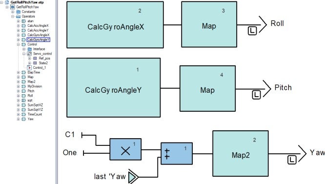
The strength of the stabilization algorithm lies in the mathematical functions and operators we declare in Ansys SCADE. These operators facilitate the calculation of angles and the control of servo movements.
Operator Declaration
Operators in SCADE are essentially building blocks of the algorithm. They can be user-defined or imported, providing flexibility in how we structure our calculations.
Examples of Operators Include:
- CalcAccAngleX: Computes the angle of rotation around the X-axis.
- SumSqrtXZ: Calculates the square root of the sum of squares for the X and Z accelerometer readings, used in angle calculations.
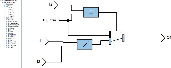
- MyDivision: Ensures safe division operations, preventing division by zero errors.
Each operator is defined to carry out specific calculations and is seamlessly integrated into the overall control logic.
Example: The MyDivision Operator
The MyDivision operator is crucial in ensuring safe mathematical operations. Here’s a brief overview of how it works:
By checking the denominator before performing division, we ensure that our algorithm remains robust, even in edge cases.
State Machine Control
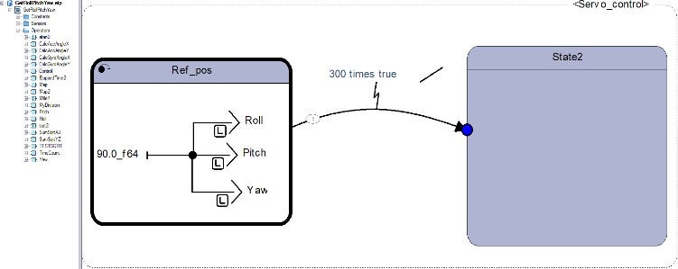
To manage the stabilization process effectively, we implement a state machine within the algorithm. The state machine transitions between different phases: one for bringing the platform to the reference position and another for actual stabilization.
Integrating Ansys SCADE with Arduino IDE
Once the stabilization algorithm is developed and tested in Ansys SCADE, the next step is to integrate it with the Arduino IDE. This integration is crucial for uploading the generated code to the development board.
Simulation and Code Generation
Ansys SCADE offers a simulation feature that allows us to visualize the system’s behavior before deploying it. Once we are satisfied with the results, we can generate the necessary code using the KCG option. This code is tailored for Arduino, simplifying the upload process.
Steps for Integration:
1. Code Generation: After successful simulation, use the KCG tool to generate the Arduino-compatible code.
2. Library Management: Each operator is declared as a library within the Arduino IDE, allowing for easy access and management.
3. Setup and Loop Functions: In the Arduino IDE, we define two main functions: setup (initialization) and loop (continuous operation). The setup function establishes communication with the sensors and servos, while the loop function processes data and sends control commands.
This streamlined integration process ensures that our stabilization algorithm runs efficiently on the Arduino board, allowing for real-time control and monitoring.
void loop() {
    Wire.beginTransmission(MPU);
    Wire.write(0x3B);
    Wire.endTransmission(false);
    Wire.requestFrom(MPU, 6, true);

    AccX = (Wire.read() << 8 | Wire.read()) / 16384.0;
    AccY = (Wire.read() << 8 | Wire.read()) / 16384.0;
    AccZ = (Wire.read() << 8 | Wire.read()) / 16384.0;

    Wire.beginTransmission(MPU);
    Wire.write(0x43);
    Wire.endTransmission(fa1se);
    Wire.requestFrom(MPU, 6, true);

    GyroX = (Wire.read() << 8 | Wire.read()) / 131.0;
    GyroY = (Wire.read() << 8 | Wire.read()) / 131.0;
    GyroZ = (Wire.read() << 8 | Wire.read()) / 131.0;

    // SCADE run controller cyclic function
    Control (&outC) ;

    int servo0Va1ue = map(outC.Roll, -90, 90, 0, 180);
    int servo1Va1ue = map(outC.Pitch, -90, 90, 0, 180);
    int servo2Va1ue = map(outC.Yaw, -90, 90, 180, 0);

        servo0.write(servo0Value);
        servo1.write(servo1Value);
        servo2.write(servo2Value);
}
Testing and Validation of the Stabilization
Platform
Once the platform is built and the algorithm is integrated, the final step is rigorous testing. This phase is crucial to ensure that the stabilization platform operates as expected and meets performance standards.
Testing Methodology
Testing involves both static and dynamic assessments. Static tests measure the platform’s ability to maintain stability when stationary, while dynamic tests evaluate its performance during movement.
Static Testing:
- Set the platform on a stable surface and measure its ability to maintain a fixed position.
- Assess how quickly the platform responds to minor disturbances.
Dynamic Testing:
- Conduct tests in different environmental conditions, such as wind or vibration.
- Monitor how well the platform maintains stability while in motion, such as during walking or driving.
Performance Metrics
To quantify the platform’s performance, we establish specific metrics:
1. Stability: Measured in degrees of deviation from the reference position.
2. Response Time: The time taken for the platform to adjust to changes in orientation.
3. Accuracy: The precision with which the platform maintains its desired orientation.
By analyzing these metrics, we can identify areas for improvement and ensure that the stabilization platform meets the desired specifications.
Conclusion
The development of a self-stabilized platform is a multifaceted endeavor that involves a careful balance of mechanical design, electronic integration, and sophisticated software algorithms. By harnessing the capabilities of Ansys SCADE and the Arduino platform, we can create an efficient and reliable stabilization system.
As engineers and managers, understanding the underlying principles and methodologies behind stabilization platforms empowers us to innovate and push the boundaries of technology. With the right approach, we can enhance applications across industries, from defense and aerospace to film and photography.
As we move forward, continuous improvements in sensor technology, processing power, and algorithm sophistication will further enhance the capabilities of stabilization systems. The future of stabilization platforms is bright, and those who harness these technologies will lead the charge into new frontiers of innovation.
Key Takeaways:
- Stabilization platforms rely on mechanical, electronic, and embedded software components for effective operation.
- A robust stabilization algorithm, driven by mathematical functions, is essential for maintaining orientation.
- Ansys SCADE streamlines the development process, facilitating simulation and integration with platforms like Arduino.
- Rigorous testing ensures performance meets industry standards, paving the way for successful deployment in various applications.
In closing, the development of stabilization platforms not only showcases our engineering capabilities but also exemplifies our commitment to pushing technological boundaries. The journey doesn’t end here; it’s a steppingstone towards an exciting future filled with possibilities.
Next Steps: Consider further exploration of advanced control algorithms or the integration of artificial intelligence to enhance stabilization systems even more.
About the author
Alexandru-Dragos Adam (LinkedIn) is a researcher associated with the Military Technical Academy (MTA) in Romania and is currently pursuing a PhD at the Politehnica University of Bucharest (UPB). His work primarily focuses on advanced signal processing and communication technologies. He is involved in various research projects, particularly those that deal with digital signal processing, radar systems, and machine learning applications.
-


Introducing Ansys Electronics Desktop on Ansys Cloud
The Watch & Learn video article provides an overview of cloud computing from Electronics Desktop and details the product licenses and subscriptions to ANSYS Cloud Service that are...

How to Create a Reflector for a Center High-Mounted Stop Lamp (CHMSL)
This video article demonstrates how to create a reflector for a center high-mounted stop lamp. Optical Part design in Ansys SPEOS enables the design and validation of multiple...

Introducing the GEKO Turbulence Model in Ansys Fluent
The GEKO (GEneralized K-Omega) turbulence model offers a flexible, robust, general-purpose approach to RANS turbulence modeling. Introducing 2 videos: Part 1 provides background information on the model and a...

Postprocessing on Ansys EnSight
This video demonstrates exporting data from Fluent in EnSight Case Gold format, and it reviews the basic postprocessing capabilities of EnSight.

- An introduction to DO-178C
- Scade One – Bridging the Gap between Model-Based Design and Traditional Programming
- ARINC 661: the standard behind modern cockpit display systems
- Scade One – An Open Model-Based Ecosystem, Ready for MBSE
- Scade One – A Visual Coding Experience
- Using the SCADE Python APIs from your favorite IDE
- How to Verify a Model on Host with SCADE Test? (Part 4 of 6)
- How to integrate multiple SCADE models into one executable
- Scade One – Democratizing model-based development
- Introduction to the SCADE Environment (Part 1 of 5)

© 2025 Copyright ANSYS, Inc. All rights reserved.


