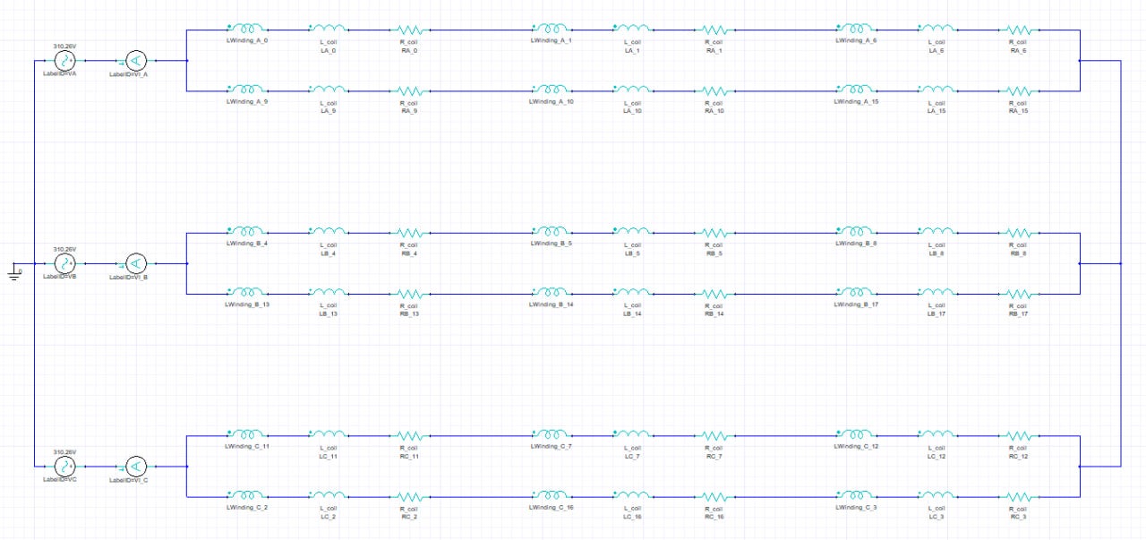
TAGGED: -Ansys-Maxwell-electronics
-
-
November 19, 2024 at 11:42 pm
jjh4804a
SubscriberI would like to know how to connect U, V, W phases with Y connections and how to set the start and end points of winding.
My program version is 2020 R1. -
December 5, 2024 at 10:17 am
Tamami Yamanaka
Ansys EmployeeHello,
In Maxwell Circuit Editor, you can create an external inverter circuit including windings and Y connection, and then connect it to Maxwell 2D/3D.
If you do not use an external circuit, the Y connection excitation setting is explained in the following help. In Maxwell 3D transient designs, the Y connection setting is supported since 2020R2 version.Maxwell Help > Assigning Boundaries and Excitations for 2D Designs > 2D Transient Boundaries and Excitations > Setting Up a Y Connection in 2D and 3D Transient Designs
Ansys Maxwell 2024 R2 - Setting Up a Y Connection in 2D and 3D Transient DesignsBulk coils are often used to simulate electrical machines, and the start and end points of U, V, W windings do not need to be considered. These coils are modeled for each slot, and after specifying the direction of current flow at the coil terminal, each coil is assigned to U, V, W windings.
-
December 28, 2024 at 6:41 pm
mohammadevs9
SubscriberHello Tamami Yamanaka
How we can create the Y connection in external circuit? Can you show any picture about it or give me any help about it?
-
December 29, 2024 at 5:27 am
mohammadevs9
Subscriberinfact I want the basic circuit that is equal to voltage excitation
-
-
-
December 29, 2024 at 5:31 am
mohammadevs9
SubscriberI got wrong results with sine source in external. I guess my source is one inverter that is equal to voltage excitation
-
December 29, 2024 at 9:30 am
Tamami Yamanaka
Ansys EmployeeHello,
In Maxwell 2021R1 and later versions, File > Open Examples > Maxwell > Electric Machines > Interior Permanent Magnet.aedt is provided as an example of an electric machine with an external inverter circuit.
For earlier versions, you can use File > Open Examples > RMxprt Examples. Circuit Type: [Y3] in the machine properties of the RMxprt project tree indicates a Y-connected three phase drive circuit. (e.g. bldc > ws-1.aedt)
After analyzing these RMxprt models, you can create a Maxwell 2D/3D motor model including the external circuit from RMxprt > Analysis Setup > Create Maxwell Design.Â
Ansys Maxwell 2024 R2 Help > RMxprt Help > RMxprt Machine Types > General Data for Brushless PMDC Motors
Ansys Maxwell 2024 R2 - General Data for Brushless PMDC MotorsAnsys Maxwell 2024 R2 Help > RMxprt Help > Postprocessing and Generating Reports in RMxprt > Creating a Maxwell Design from RMxprt
Ansys Maxwell 2024 R2 - Creating a Maxwell Design from RMxprtÂ
-
December 29, 2024 at 9:34 am
mohammadevs9
SubscriberThank you very much for your help
-
-
December 29, 2024 at 10:55 am
mohammadevs9
SubscriberI saw them but let to ask my question in another way. I got a 2D induction motor model from rmxprt. The default exitation of windings is voltage. I want to create an external circuit that be equal to default voltage exitation in maxwell. I draw the circuit and connected it to windings but the result is different from default of maxwell. what is the problem?
For example in voltage excitation for PhaseA we have: Stranded conductors, Initial current = 0 A, Resistance = 4.6218459 Ohm, Inductance = 0.0019265104H, The voltage equation: 310.26*sin(2*pi*50*time), Number of parallel branches = 2. The winding has 6 coils.
In external circuit, I have the circuit that shown in picture. I set the R and L as follows: R = 2/3*4.6218459Ohm, L = 2/3*0.0019265104H
what is the problem?
thanks! -
December 30, 2024 at 8:53 am
mohammadevs9
SubscriberOkay, I found my problem. My simulation is started from specific speed and the back emf has no effect on stator circuit.
Thank you Tamami Yamanaka!
-
- You must be logged in to reply to this topic.
- Ansys Maxwell 3D – eddy current
- Difficulty/Obstacle: “Parasolid entry check failed for part:”
- Simplorer+Maxwell Cosimulation results and Maxwell results mismatch
- Maxwell circuit – PWM
- Plotting Ex, Ey and Ez in vector forms individually
- Ansys-MATLAB Co-Simulation
- Compute near field simulation with current
- Y wiring method and the start and end points of winding.
- Calculating E-field tangential to a 2D resonant structure on a sapphire chip
- Ansys HFSS, Lumped port impedance affects Z-parameters
-
1997
-
897
-
599
-
591
-
418
© 2025 Copyright ANSYS, Inc. All rights reserved.