-
-
April 15, 2021 at 2:41 pm
Dioser
SubscriberHi everyone,
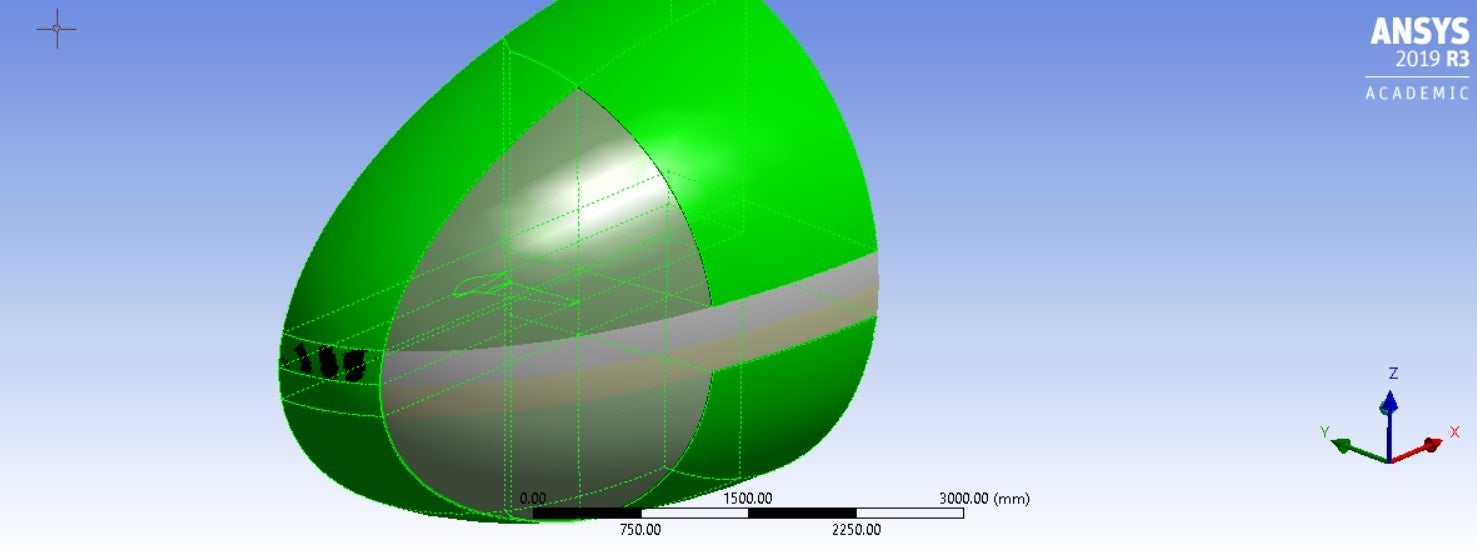
I have been working on this model for a long time now. It is a 3D wing geometry for external aerodynamics analysis. In the past, I had some success with a mesh made of tetrahedral elements only, but now that I must increase the fluid domain size drastically, tetra elements would result in such a large mesh that it would be prohibitive. I have seen many examples for similar problems, but they either use ICEM for meshing (which I do not have access to) or just use tetrahedral elements in a very small fluid domain (which does not help my case here). So the challenge is to use Ansys Workbench Meshing for this.
So right off the bat, I have "cleaned" and decomposed the geometry into sweepable bodies, according to this Ansys Tutorial series that someone here recommended (Thanks!) https://www.youtube.com/watch?v=P19GOTQWmc0&t=95s
It resulted in the following sweepable bodies:
April 15, 2021 at 4:03 pmRob
Forum ModeratorLook through the sizes you've set. With a curvature minimum of 0.1mm and a domain that's many metres long you might be trying to put a few million cells on the wing. Unfortunately to model aircraft parts properly you do need a fairly high cell count. nApril 15, 2021 at 4:20 pmSubscriberHi Rob,nThanks for your answer. Yes, I am expecting the cell count to be pretty high. But with the Hex mesh, it should not be as high as when using tetra. That is the reason for trying to generate a Hex mesh. Do you think the error is related to the number of elements?.April 15, 2021 at 4:51 pmDrAmine
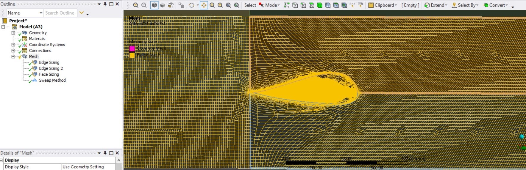
Ansys EmployeeYou can try relying on non conformal mesh to just have fine resolved mesh in the wing zone part leave other coarse or coarseness gradually. You can first try with larger curvature value to see if it meshes and based on that you elaborate on different Meshing strategynApril 16, 2021 at 2:45 pmSubscriberHi DrAmine,nThanks for the suggestion. So for a non conformal mesh all I have to do is to not share topology between the bodies? What would be the benefit of having a non conformal mesh in this case?nApril 16, 2021 at 2:59 pmForum ModeratorNon conformal means if the problem is due to the cell size interaction at the volume boundaries you'll have a mesh and can see where the problems are. If the cell sizes are too different you'll see a discontinuity in the result. As a test tet the volumes immediate around the aircraft then see if you can sweep the remaining volumes: mesh it block by block. nApril 21, 2021 at 2:49 amSubscriberArrayThanks for the suggestion. I tried that and the result was a failed mesh, like in the pictures below. When seeding tets, it just did not mesh the second volume. When seeding hex, the mesh was too skewed towards the boundaries of the volumes.n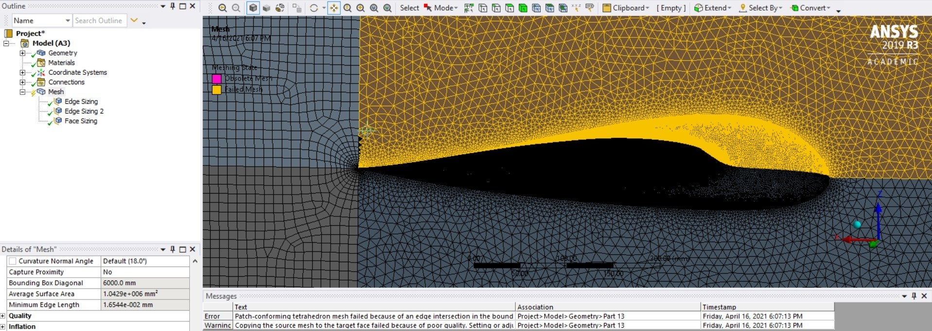
 I don't really know how to build this kind of hex mesh in workbench. I tried using Fluent CFD meshing instead, with the watertight geometry workflow. Almost everything right, until it was time to generate the volume mesh. I got some error from the previous step and the Create volume mesh does not display anything. Any idea about what this could be? Also, in your opinion, is it better to use this Fluent Meshing instead of workbench meshing?n
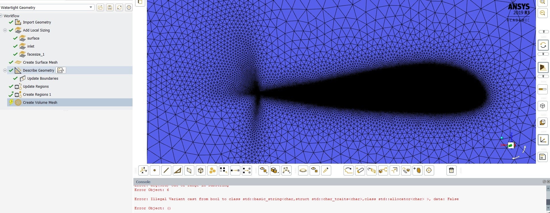 Thanks!n
April 21, 2021 at 3:17 amSubscriberAnd there is also this quirky thing on updating boundaries:n
Thanks!n
April 21, 2021 at 3:17 amSubscriberAnd there is also this quirky thing on updating boundaries:n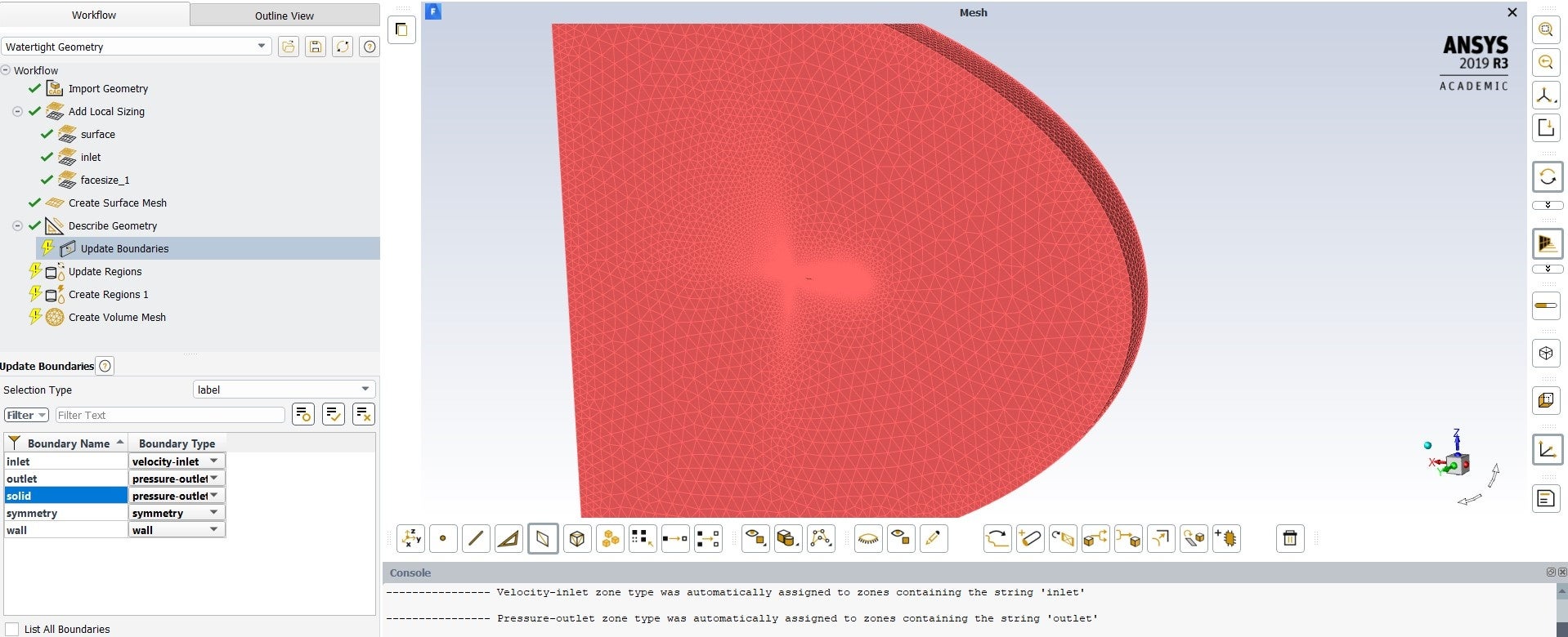 Even though my geometry has no solids, and I described it as consisting of only fluid regions, the program automatically creates this solid boundary, which has an pressure-outlet type of boundary. I am presuming that this is behind the issue of my previous comment. Sounds reasonable?n
April 21, 2021 at 11:14 amForum ModeratorThe solid label is because the tools assign any volumes a solid label and unlabelled surfaces in Fluent Meshing can then inherit that name. You'll have missed a surface somewhere when setting the named selections. I wouldn't expect to see the odd cell clustering at the trailing edge so check the surfaces and surface mesh in that region. nRe the Workbench Meshing images, check the edge sizing you've assigned and also the surface mesh option and source face for sweep:it looks like some constraints are clashing. nApril 21, 2021 at 5:24 pmSubscriberArrayI did all named selections again, this time making sure that I extended all faces to their limits when assigning named selections. The result is the same, with the same surface mesh and errors. Still can't access the volume mesh step. Anything else that could be the reason for this? About the clustering of cells on the trailing edge, I think that is due to the curvature refinement to resolve the small radius.nAnd that solid boundary still remains. Fluent assigns a wall-type bc to it automatically, I don't know why.n
Even though my geometry has no solids, and I described it as consisting of only fluid regions, the program automatically creates this solid boundary, which has an pressure-outlet type of boundary. I am presuming that this is behind the issue of my previous comment. Sounds reasonable?n
April 21, 2021 at 11:14 amForum ModeratorThe solid label is because the tools assign any volumes a solid label and unlabelled surfaces in Fluent Meshing can then inherit that name. You'll have missed a surface somewhere when setting the named selections. I wouldn't expect to see the odd cell clustering at the trailing edge so check the surfaces and surface mesh in that region. nRe the Workbench Meshing images, check the edge sizing you've assigned and also the surface mesh option and source face for sweep:it looks like some constraints are clashing. nApril 21, 2021 at 5:24 pmSubscriberArrayI did all named selections again, this time making sure that I extended all faces to their limits when assigning named selections. The result is the same, with the same surface mesh and errors. Still can't access the volume mesh step. Anything else that could be the reason for this? About the clustering of cells on the trailing edge, I think that is due to the curvature refinement to resolve the small radius.nAnd that solid boundary still remains. Fluent assigns a wall-type bc to it automatically, I don't know why.n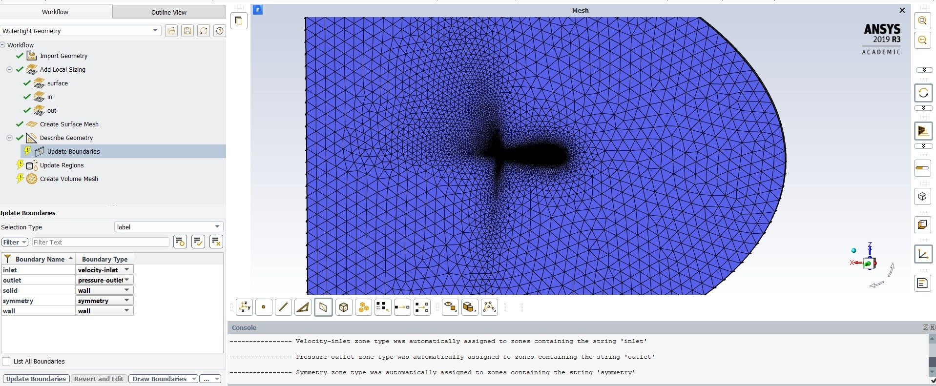 nn
April 22, 2021 at 8:34 amForum ModeratorZoom into the regions with the overly fine mesh and see if there's anything odd happening. Also make sure the surfaces are as you're expecting them. nIs this a swept section of an airfoil? If so, why can't we see through the hole where the fluid isn't present?nApril 26, 2021 at 3:34 pmSubscriberThe surfaces are fine. It is a finite wing, we can't see through the hole because the surface mesh is pretty fine, so it gets too dark to see the outline, but it is there. The picture below shows what the surface looks like. Thankfully I got the volume mesh step to work. I don't know what I did though nn
nn
April 22, 2021 at 8:34 amForum ModeratorZoom into the regions with the overly fine mesh and see if there's anything odd happening. Also make sure the surfaces are as you're expecting them. nIs this a swept section of an airfoil? If so, why can't we see through the hole where the fluid isn't present?nApril 26, 2021 at 3:34 pmSubscriberThe surfaces are fine. It is a finite wing, we can't see through the hole because the surface mesh is pretty fine, so it gets too dark to see the outline, but it is there. The picture below shows what the surface looks like. Thankfully I got the volume mesh step to work. I don't know what I did though nn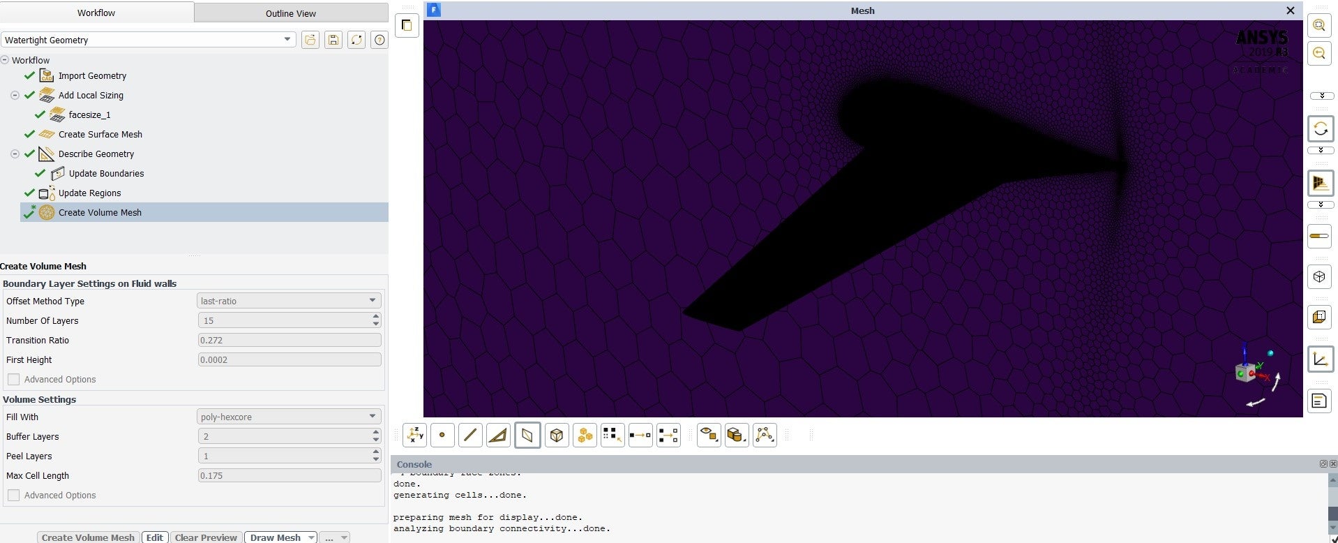 nn
April 26, 2021 at 3:50 pmForum ModeratorExcellent. How is the quality? nApril 26, 2021 at 5:15 pmSubscriberThere are no skewed cells (> 0.9). Maximum skewness is 0.80. Minimum orthogonal quality is 0.2 . nConsidering that the last mesh I created with this method has 10,090,749 cells, I think it is pretty good, right?.ow I need to figure out better parameters for the inflation layer. I calculated the first cell height for a desired Y+ value of 1 for this model, which gives a height of 0.1 mm. I am using the last-ratio offset method, with 20 layers and I tried a transition ratio of 0.5 . The inflation came out great but the total thickness is still too thin, around 5 mm, which is far from my BL estimate for a turbulent plate. How can I calculate the right combination of transition ratio and number of layers to obtain the desired total thickness? I was looking for explanations in the forum and in the manual, but they usually talk about other methods which use growth rate instead of transition ratio.n
nn
April 26, 2021 at 3:50 pmForum ModeratorExcellent. How is the quality? nApril 26, 2021 at 5:15 pmSubscriberThere are no skewed cells (> 0.9). Maximum skewness is 0.80. Minimum orthogonal quality is 0.2 . nConsidering that the last mesh I created with this method has 10,090,749 cells, I think it is pretty good, right?.ow I need to figure out better parameters for the inflation layer. I calculated the first cell height for a desired Y+ value of 1 for this model, which gives a height of 0.1 mm. I am using the last-ratio offset method, with 20 layers and I tried a transition ratio of 0.5 . The inflation came out great but the total thickness is still too thin, around 5 mm, which is far from my BL estimate for a turbulent plate. How can I calculate the right combination of transition ratio and number of layers to obtain the desired total thickness? I was looking for explanations in the forum and in the manual, but they usually talk about other methods which use growth rate instead of transition ratio.n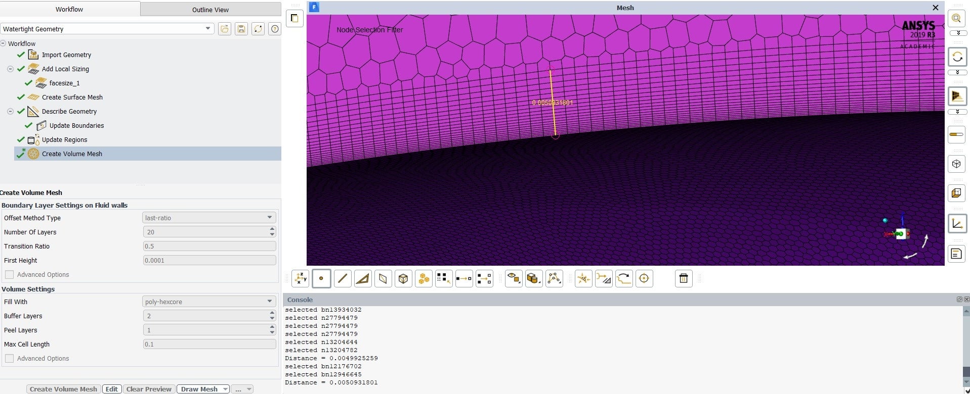 n
April 27, 2021 at 9:42 amForum ModeratorGetting the inflation layer to the correct thickness is part art, part calculation and part luck. I'd cheat and figure out the total thickness and then use anisotropic adaption to fix the near wall cell height. I mainly deal with multiphase so y+ and inflation aren't something I worry about as much as my counterparts who model aeroplanes and cars though. nApril 27, 2021 at 3:13 pmSubscribernWhere can I find this anisotropic adaption? I couldn't find much about it and I don't see it in my Fluent screen. Is it something you do after the solution is computed, like other kinds of mesh adaption?nThanks for the help!nApril 27, 2021 at 3:25 pmForum ModeratorIt's moved again, look in Adaption - Refine/Coarsen and Advanced Controls. You'll need to create a register (probably boundary) and also select the boundary of interest in the panel. nViewing 16 reply threads
n
April 27, 2021 at 9:42 amForum ModeratorGetting the inflation layer to the correct thickness is part art, part calculation and part luck. I'd cheat and figure out the total thickness and then use anisotropic adaption to fix the near wall cell height. I mainly deal with multiphase so y+ and inflation aren't something I worry about as much as my counterparts who model aeroplanes and cars though. nApril 27, 2021 at 3:13 pmSubscribernWhere can I find this anisotropic adaption? I couldn't find much about it and I don't see it in my Fluent screen. Is it something you do after the solution is computed, like other kinds of mesh adaption?nThanks for the help!nApril 27, 2021 at 3:25 pmForum ModeratorIt's moved again, look in Adaption - Refine/Coarsen and Advanced Controls. You'll need to create a register (probably boundary) and also select the boundary of interest in the panel. nViewing 16 reply threads- The topic ‘Why won’t Ansys generate a Hex mesh for this geometry?’ is closed to new replies.
Innovation Space Trending discussions
 Top Contributors
-
peteroznewman
 6465
6465 -
scabo
 1906
1906 -
Dennis Chen
 1458
1458 -
javat33489
 1308
1308 -
Shyam Prasad V Atri
1022
Top Rated Tags
© 2026 Copyright ANSYS, Inc. All rights reserved.
Ansys does not support the usage of unauthorized Ansys software. Please visit www.ansys.com to obtain an official distribution.
-
Ansys Assistant will be unavailable on the Learning Forum starting January 30. An upgraded version is coming soon. We apologize for any inconvenience and appreciate your patience. Stay tuned for updates.