

-
-
February 25, 2022 at 8:26 am
KSD
SubscriberI want to specify exact Mach number = 1, at inlet of divergent section of nozzle.
I have used isentropic relations to find the static pressure corresponding to M = 1 and given stagnation pressure and I am specifying the same values at Pressure inlet boundary condition.
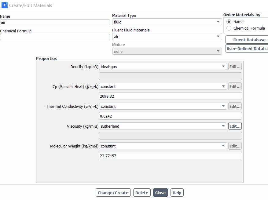
And I am using air with specific heat ratio = 1.2, R = 349.7208 not the default value of 1.4 and Mw = 28
So to consider that difference, I am finding Specific Heat Cp using this relation [ y*R/(y-1) ] , then the molecular weight using the relation [ Universal Gas Constant/R ] and substituting in Air Material section.
February 28, 2022 at 4:44 pmSubscriberSir Could you please help.
March 1, 2022 at 4:18 pmSubscriberCan anyone help me please. I literally don't know the reason for it.
March 1, 2022 at 4:23 pmKalyan Goparaju
Ansys EmployeeHello,
Have you tried setting the inlet to a velocity-inlet and specifying the appropriate velocity and pressure? That should ensure the correct inlet Mach number.
Kalyan
March 1, 2022 at 7:42 pmSubscriberSir, I am actually trying to solve supersonic viscous compressible cross flow problem through the diffuser using density based solver with k-w-SST turbulence model .
And I want the Mach number at the throat to be 1.
And I have read that, velocity inlet will give non physical answers when used for compressible flow. So, I doubt whether it is valid to use it or not.
Still I have run the simulation using both velocity inlet and mass flow inlet.
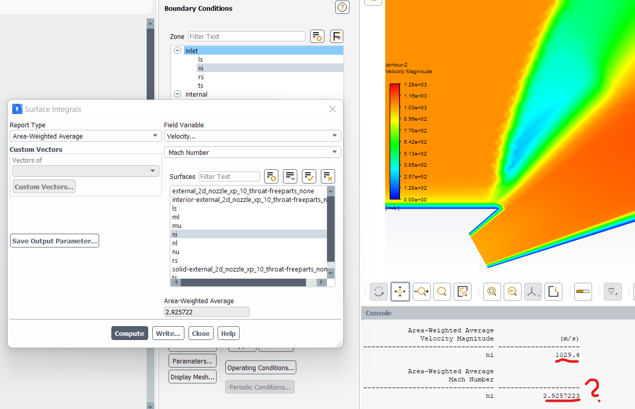
These are the results I am getting, Velocity at inlet corresponding to M = 1 is 1029.4 m/s using the relation V = sqrt(y R t) * M
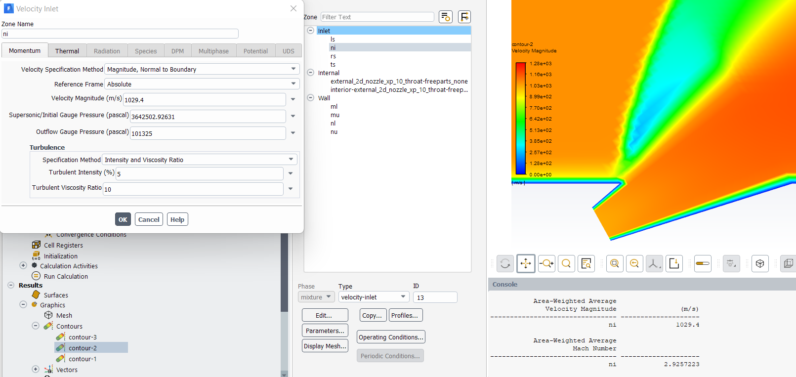 And I can see that my area weighted avg at the inlet is exactly matching the given specified velocity at velocity inlet boundary condition, but area weighted average of Mach number at inlet, I am getting is 2.9257 instead of 1 which way off than I had using pressure inlet boundary condition.
 But when I use mass flow inlet as inlet boundary condition, by specifying mass flow rate using choke nozzle relation. I am getting Mach number like around 1.23 but not exactly as 1.
Could you please tell me why is it happening like this?
March 2, 2022 at 1:47 pmRob
Forum ModeratorWhat does the mesh look like?
Choke condition assumes the downstream region is "clear". If the gas doesn't clear the region does the back pressure influence the flow?
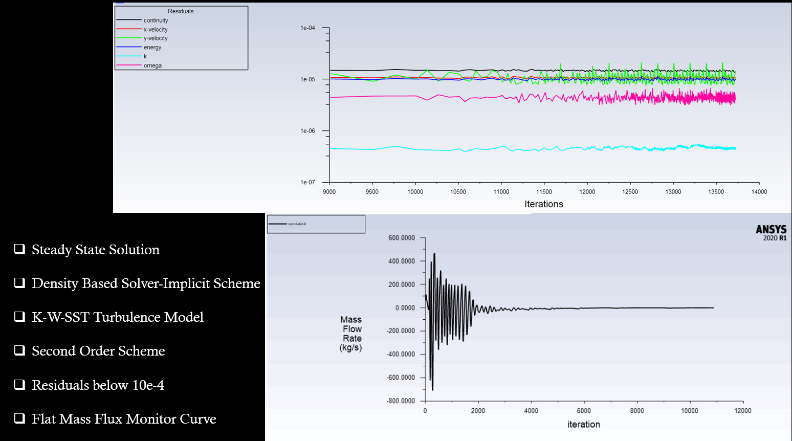
March 3, 2022 at 6:10 amSubscriberSir, I have done the simulation and it is converging and the mass flux, drag monitor is also a flat curve without any fluctuations.
 I don't think there are any problems related to mesh around diffuser inlet as it is structured mesh.

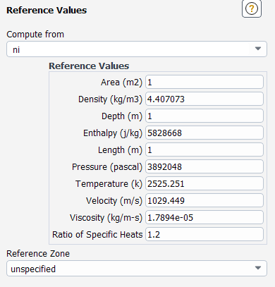
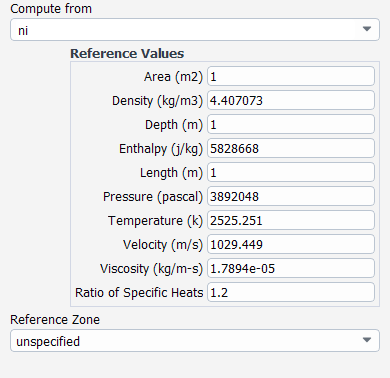
 Sir, Is it anything related to reference values I have entered ? As it is a 2D problem, considering depth of 1m and diameter of diffuser inlet as D. I have specified both depth, as diameter of nozzle inlet and area as (1*D).
And rest of the parameters in reference value box are the default values.
But still even my probe value is also around 1.2 which doesn't make sense to me. Can you tell me where I am going wrong.
March 3, 2022 at 10:28 amForum ModeratorLook at the flow pressure, temperature etc in the domain. If you're heating/cooling etc then several things will change and that then alters the Mach Number. It's hard to know without looking at the case (which we can't do) and without high speed compressible flow experience (which I haven't got). You've also got an expansion immediately after the inlet and that may play a part in the difference.
In 2D you're looking at a slot rather than a round port. Leave the reference as 1m, but look into whether slots behave differently to round jets. Just a thought - I don't know the physics well enough to advise. may know more.
March 3, 2022 at 11:01 amSubscriberSir, Sir, I am just specifying supersonic inlet at diffuser inlet BCs and rest as Fairfield BCs except walls.
Yeah at diffuser inlet I am specifying Stagnation Pressure = 6.895 Mpa, Stagnation Temperature = 2777.7778 K and Static pressure corresponding to Mach number 1 using isentropic relationship.
And for Fairfield BCs I am specifying Supersonic Mach number and atmospheric BCs.
Yes sir it is under expanded jet case, Is it related to Compressible gas flow? As viscous and ideal gas is present so Value will not match exactly by using simple isentropic relations?
Or do I have to use some empirical relations?
Sir Could you please help?
March 7, 2022 at 8:36 amSubscriberDoes anyone know what might be the reason for such results.
It would be really helpful if you can me tell me the reason for it.
March 7, 2022 at 12:16 pmDrAmine
Ansys EmployeeFirst of all be patient. Second try to summarize the problem again with recent status update. One question I have: did you change the the isentropic exponent in the reference values?
March 7, 2022 at 12:52 pmSubscriberSir, I am solving 2D Steady Under expanded Jet Crossflow Interaction.
By Using Following Settings In Ansys Fluent
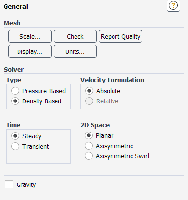
Under General Tab
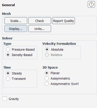 I have checked the scale option as well dimensions and units of domain is matching exactly as I created in Cad Modelling.
I am using k-w-SST model with default parameters with Energy Box Turned on.
Under Create Material Tab,
I want to specify exact Mach number = 1, at inlet of divergent section of nozzle.
I have used isentropic relations to find the static pressure corresponding to M = 1 and given stagnation pressure and I am specifying the same values at Pressure inlet boundary condition.
And I am using air with specific heat ratio or isentropic coefficient = 1.2, R = 349.7208 not the default value of 1.4 and Mw = 28
So to consider that difference, I am finding Specific Heat Cp using this relation [ y*R/(y-1) ] , then the molecular weight using the relation [ Universal Gas Constant/R ] and substituting in Air Material section.
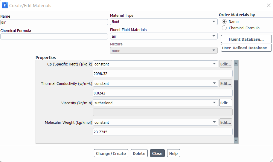 Under Reference Values, I have used compute from Diffuser Nozzle Inlet and I have explicitly specified the ratio of specific heat as 1.2 from the default value of 1.4. And I didn't change other parameters.
 Sir, I have done the simulation using Pressure inlet (Supersonic Diffuser Inlet Specifying Po, To and Static Pressure Corresponding to M = 1 using isentropic relations) and Fairfield BC (Specifying Ambient Condition and Desired External Mach Number) s and residuals are converging and the mass flux, drag monitor is also a flat curve without any fluctuations.
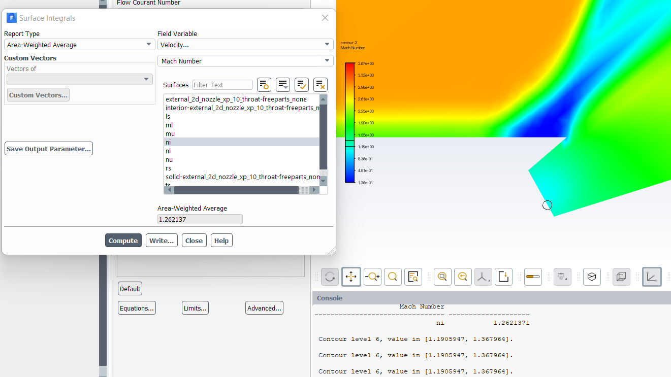
But I don't know for some reason I am not getting the exact Mach number as specified, as you can see that I have also used probe and calculatedarea averaged of 2Dinletof divergent section of nozzle it is not same as M =1.
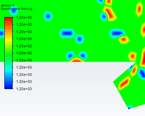
I have even checked the contour plot of gamma value to ensure that whether the changes made on air properties are applied or not, but according to the plot it seem the gamma value is same as the value I specified.
 Sir, till now following suggestions I received
1) Try Velocity Inlet :: I tried both velocity inlet and mass flow inlet but still Mach number at the diffuser inlet is not matching exactly as 1.
2) Look at Mesh :: I have Created Structured Mesh and I am also getting good converged solution So i don't think that is the reason for it.
3) Are there any heating/cooling present :: I am specifying Stagnation Temp = 2777.778 K at diffuser inlet, Ideal gas air as well to accommodate the density variation across the nozzle and also energy equation is also turned on. And there are no sources present inside the domain as well.
Sir, This is the status till now, I don't know where I am going wrong. Could you tell me what might be the reason for it. Why instead of sonic flow at inlet, I am getting some other value of Mach number.
March 7, 2022 at 1:14 pmSubscriberSir, I am solving 2D Steady Under Expanded Jet Crossflow Interaction.
In Ansys fluent settings
Under General tab
 I have check the scale, the domain dimensions and units are exactly matching as I have made in CAD modelling.
I want to specify exact Mach number = 1, at inlet of divergent section of nozzle or I want sonic Diffuser Inlet
I have used isentropic relations to find the static pressure corresponding to M = 1 and given stagnation pressure and I am specifying the same values at Pressure inlet boundary condition.
And I am using air with specific heat ratio or isentropic coefficient = 1.2, R*= 349.7208 (Gas Constant) not the default value of 1.4 and Mw = 28
So to consider that difference, I am finding Specific Heat Cp using this relation [ y*R/(y-1) ] , then the molecular weight using the relation [ Universal Gas Constant/R* ] and substituting in Air Material section.
 And Under Reference Value, I used Compute From Diffuser Nozzle Inlet and explicitly specified isentropic coefficient as 1.2 instead of default value of 1.4
 Under Cell Zone section also I have ensured that my cell zone contain the fluid which I have specified.
Sir, I have done the simulation and residuals are converging and the mass flux, drag monitor is also a flat curve without any fluctuations.
But I don't know for some reason I am not getting the exact Mach number as specified, as you can see that I have also used probe and calculatedarea averaged of 2Dinletof divergent section of nozzle it is not same as M =1.
I have even checked the contour plot of gamma value to ensure that whether the changes made in air properties are applied or not, but according to the plot it seem the gamma value is same as the value I specified.
Till now following suggestion I received:
1) Try Velocity Inlet :: I tried both velocity and mass flow inlet but still the mach number at the diffuser inlet is not matching.
2) Mesh Check :: I have created structured mesh and my solution is converging properly. I don't think this is the reason.
3) Heating/Cooling Present :: I am not specifying any sources inside the domain. I am using pressure inlet (Specifying Po, To and P corresponding to Mach = 1) and Fairfield BCs (Specifying Ambient Condition and Desired Mach Number). And also air is ideal gas and energy box is turned on.
Sir, this is the status till now. I don't know why I am not getting the sonic diffuser inlet. Could you please tell me where I am going wrong.
March 8, 2022 at 2:00 pmForum ModeratorThe downstream flow will influence the temperature & pressure in the nozzle (which is 2d, so a slot rather than being round) which will then alter the material properties. You may have done the calculations correctly, but the flow is then resulting in a different Mach Number. Alter the pressure and see how that influences the result. We do CFD for a reason: the empirical correlations aren't infallible.
March 8, 2022 at 7:54 pmAnsys EmployeeI agree with Rob here. Bit challenging to start at Ma equal to one. You can try to regulate that iteratively or add a convergent section . Can you add area averages of total and static pressure values as screenshots?
March 9, 2022 at 1:46 pmKarthik Remella
AdministratorHello:
I've two questions for you - 1. How deep is your convergence? 2. How many layers do you have to resolve the subsonic region near the wall?
Karthik
March 9, 2022 at 2:31 pmSubscriberSir, My Residuals Curve looks like this
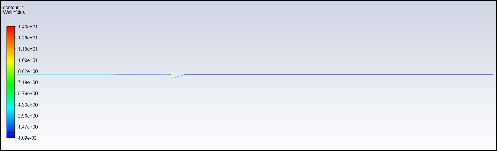
 And my first cell cell height is 1e-5 m for both outer wall and diffuser wall , but Y+ value is of order 1 for walls outside of diffuser nozzle.
 I have also done grid dependence test, and my solution are not fluctuating much with different grids.
Sir, I am right now doing that only and let you know the results later.
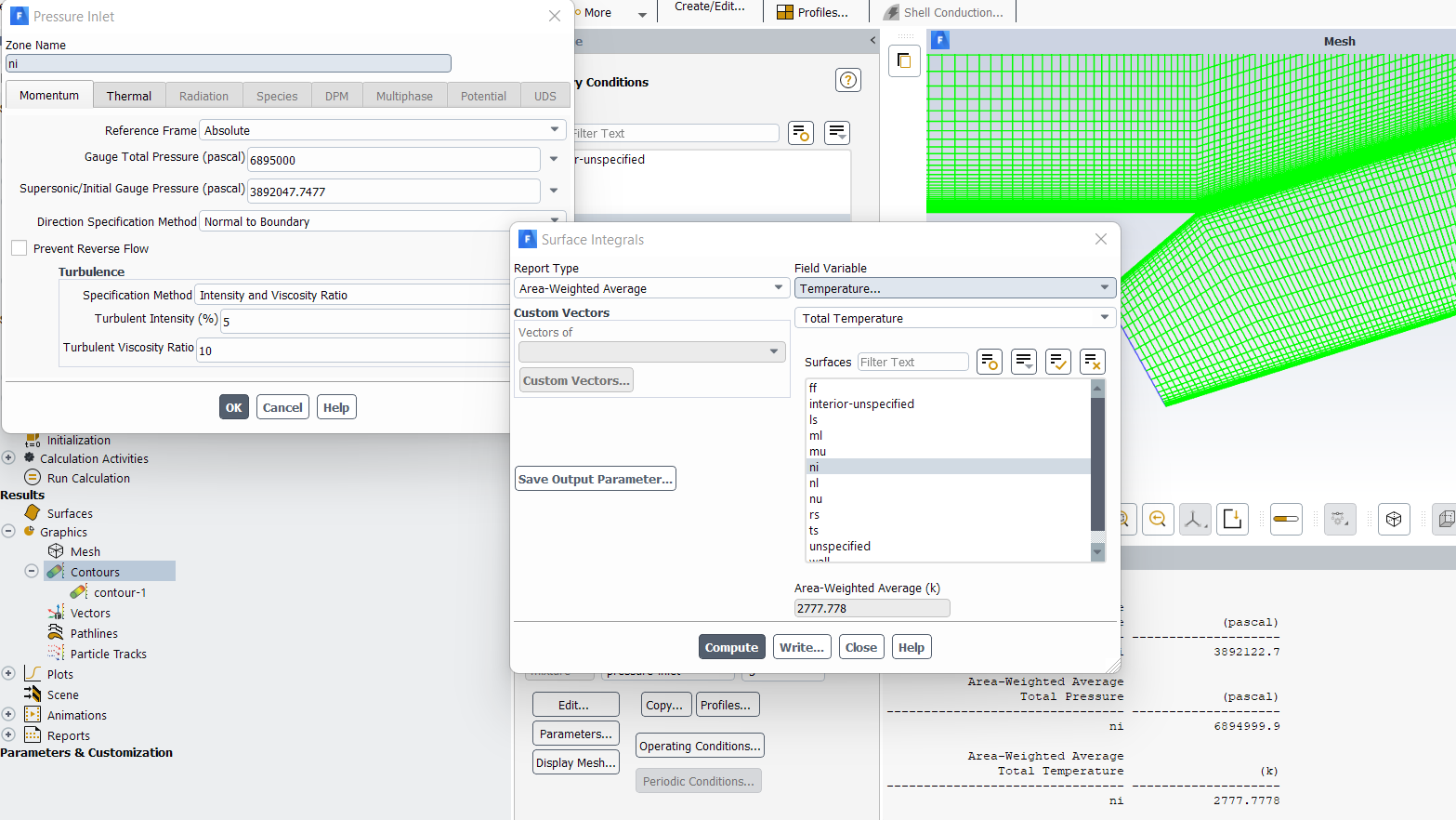
Sir the area weighted average value of Static Pressure and Total Pressure are as follows
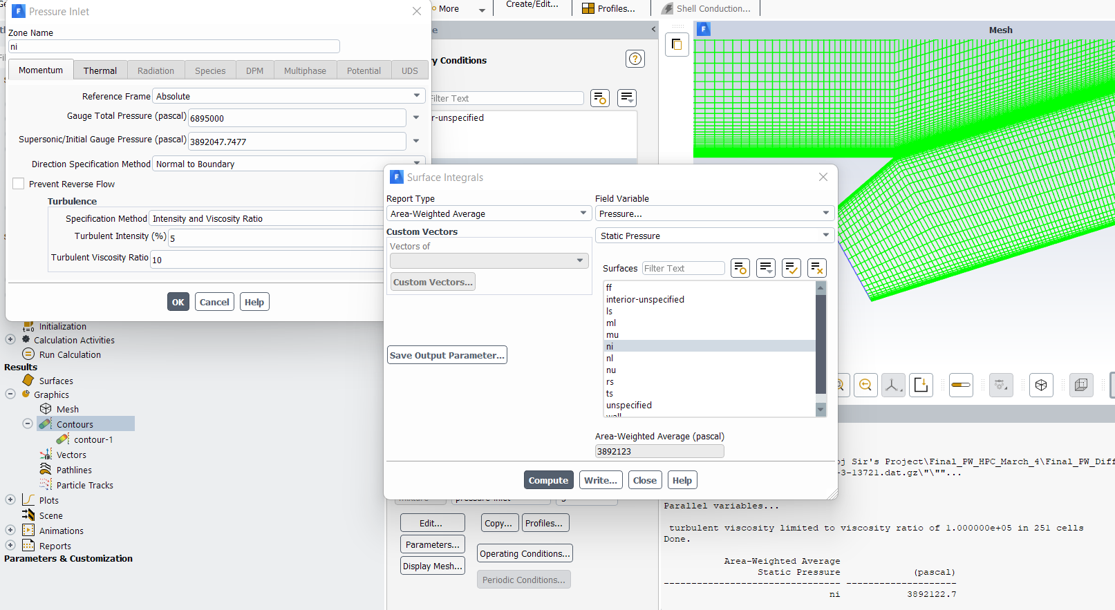
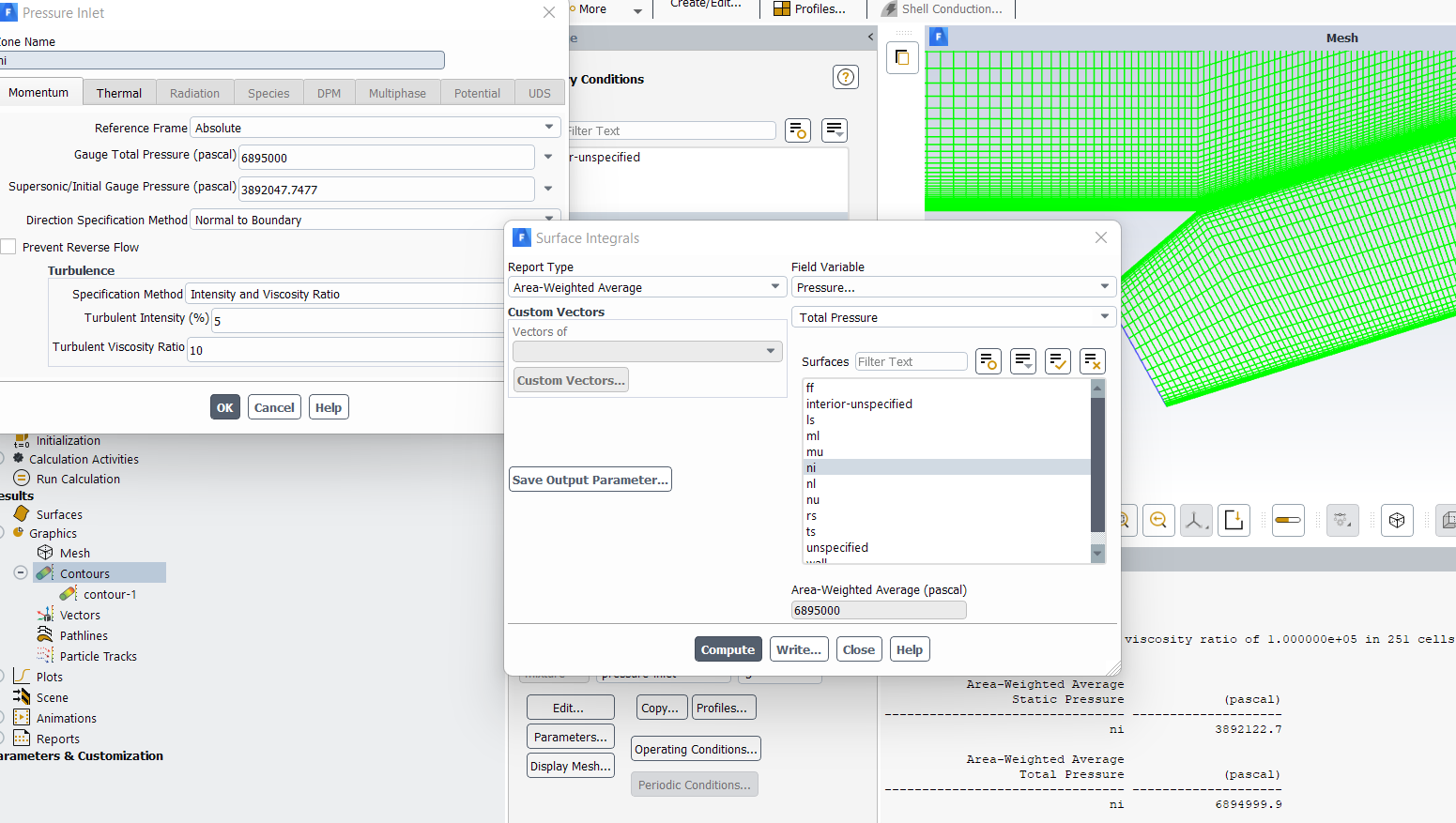 I can see that static pressure value is not exactly as I have specified in Pressure Inlet, No Idea why so even though total pressure is matching. I have also specified Stagnation temperature of 2777.778 K whose area weighted avg at inlet is also matching.
 And Sir, the reason I am not adding convergent section is because whenever I add Convergent Section, my solution varies with Supersonic/Inlet Pressure initialization as discussed in different thread where one Sir told to use UDF and change the outer pressure gradually but that also didn't work, Link for that one is here
/forum/discussion/36174/why-am-i-getting-different-flow-field-for-different-supersonic-initial-gauge-pressure#latest
That's why discarded Convergent section and using sonic diffuser inlet.
March 11, 2022 at 8:02 amSubscriberSir..
March 11, 2022 at 9:51 amAnsys EmployeeThe issue is that Ma=1 as inlet is really hard. Now the solver predicts weak supersonic flow: here the supersonic gauge pressure is used. The latter is not used if you are sonic and subsonic. I have a feeling that one needs to add a sort of control here so that you perhaps start subsonic and then regulate it up. With the values you are getting for static pressure I can get a Mach number almost 1 (0.99999) so perhaps I think it is a post-processing issue: can you check that on your side?
Viewing 18 reply threads- The topic ‘Why Not Getting Exact Mach Number As Specified At Inlet?’ is closed to new replies.
Innovation Space Trending discussions
 Top Contributors
-
peteroznewman
 5809
5809 -
scabo
 1906
1906 -
Dennis Chen
 1420
1420 -
javat33489
 1305
1305 -
Shyam Prasad V Atri
1021
Top Rated Tags
© 2026 Copyright ANSYS, Inc. All rights reserved.
Ansys does not support the usage of unauthorized Ansys software. Please visit www.ansys.com to obtain an official distribution.
-


The Ansys Learning Forum is a public forum. You are prohibited from providing (i) information that is confidential to You, your employer, or any third party, (ii) Personal Data or individually identifiable health information, (iii) any information that is U.S. Government Classified, Controlled Unclassified Information, International Traffic in Arms Regulators (ITAR) or Export Administration Regulators (EAR) controlled or otherwise have been determined by the United States Government or by a foreign government to require protection against unauthorized disclosure for reasons of national security, or (iv) topics or information restricted by the People's Republic of China data protection and privacy laws.
