
TAGGED: fixed-support, stress-concentration
-
-
December 18, 2020 at 5:30 pm
Rameez_ul_Haq
SubscriberIn the ANSYS, if we plot stresses near a support, specifically fixed support, we see that the stresses are pretty high there, relative to the rest of the structure. Why is that? What is the practical reason behind that? Is that some kind of a numerical glitch, or we would expect that to happen in the reality as well? [ofcourse the support will not be infintely rigid in reality, but still would be see a similar stress concentrations near the fixed supoorts]?nIf anyone can explain in a little dept, by the use of equations or laws, that will be very much helpful. Thank you.n -
December 19, 2020 at 8:19 amSubscriber,if you can answer this please, I would be so much thankful.nAnd also, I want to ask the reason why does the 'LARGE DEFLECTION ON' analysis sometimes not converge at directly 1s, and we have to apply the loads in parts (i.e. substeps) to make the analysis converge? What is the practical and theoretical reason behind that?n
-
December 19, 2020 at 11:08 am
user deleted
SubscribernAbout your first question: more information is needed to answer it. What is your model? How it looks like? What impacts are applied? What is the material? High stresses rate close to the supports can be related to big deformations of the model, in my opinion. Try to reduce the mesh size.nAbout the second question: you can read about this option here. Briefly, large deformation of the model applied on 1 step leads to big stiffness changes and the solution cannot converge in 1 s. n -
December 19, 2020 at 11:26 amSubscriber,I am just talking about a regular plate, as can be observed in the picture below.n
 Just considering static analysis, it is most of the times seen that the stresses near the fixed supports are very high. Rather it be a face of a solid, or an edge of a shell model. What is the scientific reasoning behind that? nI mean if you also consider a horizontal plate lying on top of two rectangular columns, and then uniform pressure is applied on top of horizontal plate. Assume I am going to make a structural analysis of this, and I only consider the horizontal plate in the analysis (ignoring the columns), then the connections of the plate (to the columns) can be considered as fixed support because the columns are relatively very rigid. The results will show me high concentrations near these fixed supports, and I would also expect them in reality [because there is literally penetration of the columns into the plate where they are connected, and force concentration due to reaction means high stress concentration in the plate there].nBut I want to know why and how does the solver know that near these fixed supports, the stresses should be relatively higher there in the plate?nAnd also about the big deformation thing you mentioned, the deformations near the support are the least, but the stresses are the highest, WHY?nI have already read the document which have linked, but my question is why does large changes in the stiffness [or stiffness matrices] would lead to the solution becoming uncoverged?n
-
December 19, 2020 at 11:29 amSubscriberalso, can this be explained that why does this create a problem for the solver in ANSYS? How and why the excessive distortion/thickness change is a problem for the solver?n
 nn
nn
-
December 20, 2020 at 9:35 pmSubscriber,can you please comment on this please?n
-
December 21, 2020 at 8:41 amSubscriber,will you please be able to clarify the concept here? I would be extremely grateful.n
-
December 22, 2020 at 1:09 pmSubscriberAnyone on this one please?n
-
December 24, 2020 at 8:06 pm
peteroznewman
SubscribernPoisson's Ratio causes the high stress at the Fixed Support on a rectangular plate subject to an axial tensile force.nYou can see Poisson's Ratio happening on the plate because it got narrower when it got longer, and that is the definition of Poisson's Ratio.nAt the fixed support, the material is trying to get narrower, but the constraint prevents that, which creates stress.nIf you edit the material properties and type 0 for Poisson's Ratio, then there will not be a high stress at the fixed support because the material will not be trying to get narrower.nAnother way to eliminate the high stress without changing the material Poisson's Ratio is to replace the Fixed Support with a Displacement where X=0, Z = 0 on the edge, while leaving Y Free on that edge. Choose one vertex in the corner and set Y = 0. For a shell model, this is not enough constraints, since the plate can rotate about that edge, so the Fixed Rotation can be added to support the remaining DOF. The plate will get narrower and shrink toward the constrained corner point, avoiding any stress in the Y direction.n -
December 25, 2020 at 7:24 pmSubscriberArray, thank you for clarifying things here nWill you be able to explain why does large changes in the stiffness [or stiffness matrices] would lead to the solution becoming uncoverged?.[Side Question:Consider the beam below;n
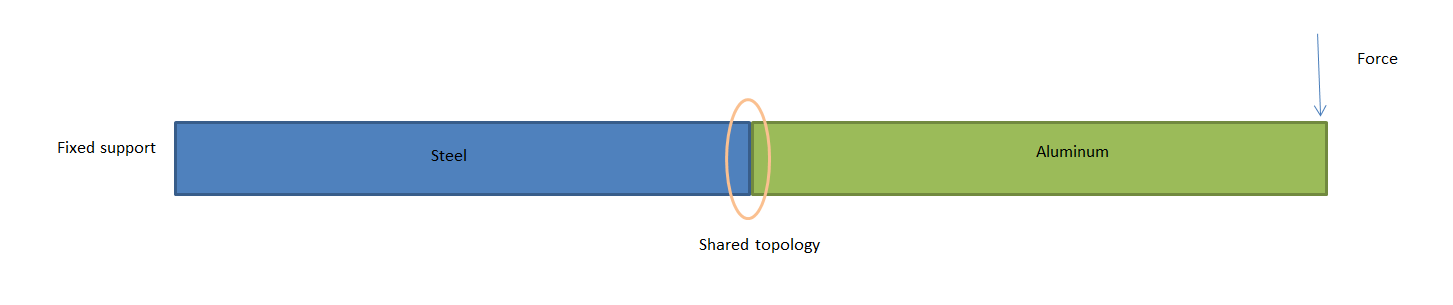 Two beams with equal and same cross section. At the shared topology region, I should expect a stress concentration I think, because there is a sudden change within the properties of the structure, where the load is flowing. I know this. I want to ask that why should I expect a stress concentration there? I mean that some say that there is a sudden change in the stiffness matrix at the shared topology region, thats why there is a stress concentration, but why would the sudden change in the stiffness matrix due to sudden change of material properties cause a stress concentration. Will it be there on both the beams? Will it happen in the reality as well?]nn And also why does an excessive thickness change or excessive distortion within an element is a problem for the solver? I know there are some tricks to avoid this error, like increase the thickness of the structure so that the stiffness increases and hence the high distortion can be suppressed, and also apply the forces in substeps (please name a few more, if there are any), but I want to ask why do we need to do that? I mean why can't the solver converge without applying any of these changes to my model? nIf the solver cannot converge due to excessive thickness change or distortion of an element, what about reality then? Is the structure failing under the same circumstances, or not failing, or something else? Thank you.n
-
December 25, 2020 at 8:29 pmSubscriber
 The animated GIF above illustrates Newton-Raphson iteration. The blue line is an unknown function, y = f(x). The search begins at an initial guess of x called x1. The value of y is computed and the slope at x1 is evaluated. Follow the slope down to Y=0 to get the next value of x called x2. Evaluate the function y2 = f(x2) and the slope at x2. Follow the slope to Y=0 to get the next value of x called x3. Continue the process until the evaluation of Y is close enough to zero to stop. nANSYS uses Newton-Raphson iteration to converge the solution of a nonlinear static structural model to the point of equilibrium. Equilibrium occurs when the difference between the internal forces and the applied forces becomes zero, like y = f(x) in the function above but in ANSYS, there is a vector of unknown displacements {x} to iterate on.n
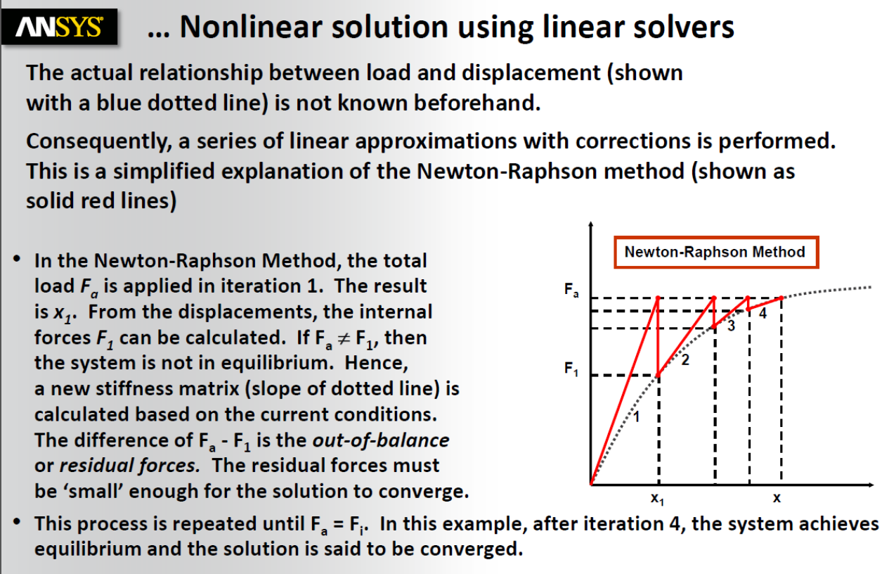
-
December 25, 2020 at 8:54 pmSubscriber
 Why do I see a stress singularity in these red marked regions, and no where else ?.I found an article explaining stress singularity: https://www.linkedin.com/pulse/stress-singularities-concentrations-mesh-fea-marcos-ac%C3%ADn-gonz%C3%A1lez/nIn this article, following picture is shown:n
 And the reason given is this:n
 I didn't understand why the corner nodes should enforce a free edge condition i.e. Normal stress equal to zero? And how does it actually cause a singularity within FEA?n
-
December 25, 2020 at 10:05 pmSubscribernWhy does a large change in stiffness result in a failure to converge?nConsider this highly nonlinear Force-Displacement graph shown below.n
 Try applying the iterative Newton-Raphson method on this function to find the unknown value of x for an applied load of Fa. Draw the sequence of trial values of x, starting at 0, and see how following the slope at each trial value will shoot the next trial value away from the correct value. The solver will only make a few iterations to try to converge on the correct value before it gives up. By forcing the solver to take many substeps, it should succeed in finding the correct value.n
-
December 26, 2020 at 1:57 pmSubscriberthat was a very good article, thank you. nThis video explains the difference between an acceptable singularity and a stress concentration. https://www.youtube.com/watch?v=-OHXl-mvR5U&ab_channel=DatawaveMarineSolutionsnHere is a good video on singularities. https://www.youtube.com/watch?v=ZP9nh4GOkIc&ab_channel=SimuTechGroupn
 A simple way to understand a singularity in FEA is when a point force is applied to a single node on a solid body. Stress = Force / Area but the area of a single node is zero, and when you divide by zero, the answer is infinity.nIn the clamped end example above, the material is shrinking in the Y axis due to Poisson's Ratio. Away from the clamped end, the Y component of stress is zero. There is a Y component of force on each clamped node (except the center node is zero) to stretch the clamped edge to its fixed value. The Y component of force gets larger the further the node is from the center on the clamped edge. But there is no area at the corner node.n
-
December 28, 2020 at 12:12 pmSubscriberThank you, I saw the video and it was quite helpful into getting an insight that how is a singularity actually caused because of mathematics in the solver's background.nHowever, I want to ask one more thing here. Since you can see in the picture that I have shared already, there is a stress concentration near the fixed end, and it persists for a few elements before it. I am just applying a force in the X direction initially on the right end, and I know that there must exist a vertical Y direction force on the nodes in the left end. But for some length/elements before the fixed end, the stress concentration indicates that there is also a force there in the Y direction. At the same time, I have only applied an external force in the X direction. So what I want to ask is that this Y direction force will also influence the load path in that region of the structure, which we should experience just because of the external force applied in X direction? What I mean to say is that the overall load path in that region will be a combination of the X force and also the Y force experienced there, right? IN THE REALITY as well (assuming the boundary condition implemented exactly mimics the reality).n
-
December 28, 2020 at 2:31 pmSubscribernThe singularity at the corner node is a mathematical artifact of the finite element method, which delivers an infinite stress at the corner.nAway from the corner, there are , in reality, internal forces that are equal and opposite from the top half to the bottom half that stretch the material out to the fixed dimension at the base. The Vector Principal plot will show the arrows horizontal at the right end, but changing angle to point toward the top and bottom corners at the left end.n
-
December 29, 2020 at 9:48 amSubscriberthank you once again. So what you have said implies that the stress concentrations which starts to form a few elements before the left end boundary condition is real because of the existence of force in the Y direction at the left end. This force in the Y direction actually makes the stresses in those few elements to rise, and the load paths (or the vector principal stresses) will be a result of the stress in the X direction (due to external force) and the stress in the Y direction (arising due to fixed left end boundary condition).nHow do we determine critical distance, in this case, of the singularity happening at the top and bottom corner nodes of the left end? [beyond which the St. Venant's principal is going to be valid].n
-
December 29, 2020 at 1:34 pmSubscribernThe distance for a stress disturbance to be significantly reduced is 2 times the maximum dimension in the cut face. It is not a critical distance, just a guideline.nYou other question shows an example of this. /forum/discussion/comment/101294#Comment_101294nHere is a video on that. https://www.youtube.com/watch?v=Fv23fkX0YhQn
-
January 13, 2021 at 11:34 amSubscriberArray, since we have already discussed about the convergence of the solver in this thread, I won't be opening another thread and will try to ask my concern here.nWhile conducting some analysis, I encountered an error something like this.n*** ERROR ***nSolution not converged at time 0.1.n ORnSolution not converged at time 0.5 (or 0.6 or 0.7 or 0.n ORnSolution not converged at time 1.nI want to ask how are these errors different from each other? nWhat kind of factors can cause these errors to occur? A general idea would help. Can geometry be a problem, maybe mesh, maybe boundary or loading condition, maybe contact, or something else? How could any of these be a problem for convergence?n
-
January 13, 2021 at 12:26 pmSubscribernThey are all the same error but there can be different corrective actions based on the shape of the N-R Force Convergence Plot. Look at the image below. See how from iteration 40 to 56, the purple curve was almost about to cross the aqua curve and convergence would have happened, if only the solver kept iterating, but it stops after 26 iterations.n
 The corrective action is to tell the solver to keep going with the NEQIT command. Read this discussion: n/forum/discussion/2550/understanding-force-convergence-solution-outputnThen there are the N-R Force Convergence Plots where the two curves just remain parallel and never trend toward crossing one another. In that case, more iterations won't help. n
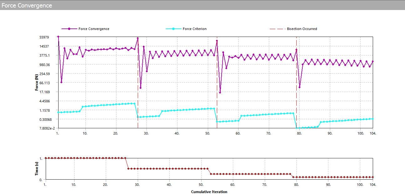 This lack of convergence is sometimes caused by elements that are too large or poorly shaped, and cannot find equilibrium. The corrective action is to remesh with smaller, better shaped elements. But you have to know which elements have the problem, and this is where the maximum value on the Newton Raphson Residual plots under the Solution Information folder show you where those elements are.n
-
January 13, 2021 at 12:28 pmSubscribern
-
January 13, 2021 at 2:35 pmSubscriber,what about the loading conditions? If I have a set of loading conditions for which the solution is converging, is it possible for another set of loading condition to make the solution to not converge? (assuming that sufficient number of substeps were provided so that the loads were not applied all at once, but in steps).nIs it possible that the lack of stiffness within a region of the model (due to low thickness of the solid or shell elements) can cause the solution to become uncoverged? Because I have once tried increasing the material within the region which was showing high Newton-Raphson residuals, and the mesh was pretty fine there, but when I increased the thickness within that region, the solution converged. I still am unaware of how increasing the thickness within a region showing high residuals will cause the solution to converge.n
-
January 13, 2021 at 10:52 pmSubscribernHigh deformation causes convergence challenges. You may have seen the Highly Distorted Element error which can stop iteration. If the section is thin, then it is easy for the load to create high deformation in that region. Increase the thickness and the deformation is reduced, making convergence easier to achieve.nA load change can take a thin section that was under tension and seeing very little deformation go into bending and it will now see high deformation.n
-
January 14, 2021 at 8:15 amSubscriber,instead of increasing the thickness, if I increase the number of substeps for the convergence, is it a good approach? Will it then converge? Will I still see high distortion of the elements?nAnd what does high distortion of the element actually means? Does it mean the element itself is deforming alot like this:n
 Or does it mean the element has translated too much from its original location during analysis?n
-
January 14, 2021 at 2:25 pmSubscribernThere are cases where more substeps will not help the convergence, a remesh is required.nDeformation is shape change of the element, not rigid body motion of the element centroid.n
-
January 14, 2021 at 3:27 pmSubscriber,Sir I know that a remesh might be required where more substeps/iterative steps will not help in convergence because you have already mentioned that in your previous comments. I am asking can a high distortion of element problem can be solved by increasing the substeps/iterative steps, or a refined mesh? (Instead of increasing the stiffness of the element by making it more thick).n
-
January 14, 2021 at 11:56 pmSubscribernWhen a highly distorted element error stops the solver, it is often the case that more substeps will solve that issue. Note that there is a difference between an error stopping the solver and the solver failing to find convergence.n
-
January 16, 2021 at 6:29 amSubscriberArray, how can contact (like frictional, frictionless, rough) become a problem for convergence in my analysis? How to identify that the convergence problem is actually because of the contact and how to overcome it?nAnd also, I am going to make a statement and would like to have your approval on this one.nThe magenta color line (in the Newton-Raphson Force convergence plot) represents the difference in the force vector between the applied force vector (for the global model) and the internal force vector (for all the nodes in the global model). This line need to have a value less than the teal line (which is basically a default value of 0.5% of the applied force vector) so that the system is considered to have converged (i.e. the equilibrium has been reached) and the solution then proceeds for the next time step'' nThere are so many nodes in the global model (each having an internal force) and on top of that the external force is also a vector, however we just see a single value of the magenta line and teal line on the force convergence plot for a sepcific iteration of a certain time step; why is that?nIs it possible if the magenta line starts below the teal line? Can it still cause any convergence difficulties?nWhy do we always observe the force convergence plot, although we have the availability of the displacement and moment convergence as well? Does all of them need to converge simultaneously in order to achieve an equilibirum within the system?.
-
January 19, 2021 at 4:02 pmSubscriberArray, an answer from you will be so much helpful on this one n
-
January 25, 2021 at 8:20 amSubscriber,can you kindly give your views on this please?n
-
January 25, 2021 at 3:13 pmSubscriberhow can contact (like frictional, frictionless, rough) become a problem for convergence in my analysis? How to identify that the convergence problem is actually because of the contact and how to overcome it?nBelow is a link to a good blog on overcoming convergence difficulties involving contact. One good way to know that contact is causing the problem is to change the nonlinear contact to Bonded contact. If that solves, you have some indication that the problem is in the nonlinear contact.nhttps://www.padtinc.com/blog/overcoming-convergence-difficulties-in-ansys-workbench-mechanical-part-i-using-newton-raphson-residual-information/nAnd also, I am going to make a statement and would like to have your approval on this one.nThe magenta color line (in the Newton-Raphson Force convergence plot) represents the difference in the force vector between the applied force vector (for the global model) and the internal force vector (for all the nodes in the global model). This line need to have a value less than the teal line (which is basically a default value of 0.5% of the applied force vector) so that the system is considered to have converged (i.e. the equilibrium has been reached) and the solution then proceeds for the next time step''nYou have the right idea but are not using the correct terminology. Read this section of the Theory manual.nhttps://ansyshelp.ansys.com/account/secured?returnurl=/Views/Secured/corp/v191/ans_thry/thy_tool10.htmlnThere are so many nodes in the global model (each having an internal force) and on top of that the external force is also a vector, however we just see a single value of the magenta line and teal line on the force convergence plot for a specific iteration of a certain time step; why is that?nBecause the solver needs a simple scalar summary metric to decide on the quality of the solution.nIs it possible if the magenta line starts below the teal line? Can it still cause any convergence difficulties?nYes, it's possible that the Force convergence starts below the teal line and it can still be a problem because of the other convergence metrics such as displacement.nWhy do we always observe the force convergence plot, although we have the availability of the displacement and moment convergence as well? Does all of them need to converge simultaneously in order to achieve an equilibrium within the system?nYes, all the convergence metrics have to converge to advance to the next load increment. Arrayn
-
January 26, 2021 at 8:29 pmSubscriber,can singularity within a geometric feature cause convergence problems?n
-
January 26, 2021 at 9:43 pmSubscriberNot usually because the singularity is only on the stress. The displacements converge.n
-
February 11, 2021 at 9:38 amSubscriberthis might be a very basic question, but can you kindly tell that what does displacement convergence actually represent? I mean that for the force convergence, it is known that the internal forces must be equal to the externally applied forces, within a certain percentage of tolerance, and the same goes with the moment convergence. But what does displacement convergence mean?n
-
March 1, 2021 at 6:14 amSubscriber,assume I am conducting a geoemtric non-linear analysis. The solution is converging if I use two substeps i.e. 0.5 sec and 1 sec. Then I conduct the same analysis using 10 substeps, i.e. o.1 sec, 0.2 sec, ......., 1 sec, and it is converging for this one as well. Should I expect a difference in the results between these two? Will the latter one be more accurate?n
-
March 1, 2021 at 10:42 pmSubscribernLook at how many iterations each one takes to get to the end.nFor example, if the 10 substep case used 2 iterations per substep, that is a total of 20 iterations.nYou might find that the 2 substep case used 10 iterations per substep, for a total of 20 iterations.nIn this example, the same amount of computation was done, the difference is how frequently output was saved.nSince the convergence criteria was the same for both cases, the accuracy should be very similar for both.n
-
March 2, 2021 at 8:27 amSubscriberThank you for your clarification.nWhat I was thinking is that since I am using two big substeps like 0.5 and 1 sec, then the force criteria value will also be higher than the ones conducted at 10 substeps. This means that the error range is higher in the former than the latter, thats why I thought maybe the latter could be more accurate than the former.n
-
March 2, 2021 at 9:14 pmSubscribernThe force criterion is the same in both cases. In the 2-step solution, on the first iteration, the force is far from the criterion, so it does 10 more until it gets below.nIn the 10-step solution, on the first substep, the force is close to the criterion on the first iteration, and it get below on the second iteration. That is because the load is only 1/5 of the 2-step solution.nThe accuracy is similar for each solution setup.n
-
March 8, 2021 at 4:58 pmSubscriber,why is that mostly the displacement converges, moment also converges but there is always a problem with the force convergence?n
-
March 8, 2021 at 6:20 pmSubscribernIt depends on the convergence values. The Program Controlled default values are 0.5% but if you turned them On, tightened up on the displacement convergence and made it 0.05%, then you would see the force converge before the displacementn
-
March 9, 2021 at 5:08 amSubscriber,well thats true but I am just asking about the program controlled default values. What I experienced is that the displacement would converge, even the moments would converge but the force convergence is usually the main issue. I mean if the force is not converging, doesn't it mean that the displacement and moment also should not converge?n
-
March 9, 2021 at 4:27 pmSubscribernThese convergence checks are mostly independent measures of solution quality and converge at different rates. You want all three to converge to have a good solution. The default convergence values are not always appropriate. In some models, I have had to decrease the displacement convergence because it did not give me the accuracy I needed for an interference fit. Using a smaller value, 100 times smaller, gave me what I needed. Once in the last 7 years did I see a model where the moment convergence was turned off because the model would not converge, and that was from a very experienced analyst. He did many other checks to assure that the solution was still of good quality. n
-
March 18, 2021 at 9:42 amSubscriber,if I want to access the Newton-Raphson residuals of the last three iterations at 0.5 secs of my non-linear analysis, although I saw the non convergence happening at 0.8 secs, is it possible to access them?n[assume program controlled is off and I have manually provided 10 substeps under the analysis settings].n
-
March 18, 2021 at 11:07 amSubscribernYou would have to set the End TIme to be 0.5 s to see the last three N-R Residuals if you only requested 3. They are overwritten in a circular buffer. You can put in a larger number so if there are 7 iterations between 0.5 and 0.8 s, then request 10 N-R Residuals.n
-
March 18, 2021 at 11:23 amSubscriber,can you also please tell us that why do we have an option of Identify Element Violations, (and when should we use it?) when we already have Newton-Raphson residuals. I mean the N-R Residuals itself most of the times mean that the elements' quality is not well enough to cause the convergence and the element itself is getting too much distorted, then why would I need to separately use the Identify Element Violations option?n
-
March 18, 2021 at 11:32 amSubscribernYou should automatically type in 3 for both N-R Residuals and Identify Element Violations on every nonlinear analysis. It creates a tiny overhead and is very useful when the solution errors out.nHowever there are two kinds of errors. nThe highly distorted elements error means some element shapes got so bad that stress could no longer be accurately calculated. You want to easily see which elements those are. Typing in a nonzero value will create a Named Selection to easily see those elements.nThe fail to converge error is when you look at the N-R Residual Force imbalance to see where the convergence is failing. There may be no highly distorted elements.nSometimes you will get both errors at the same time.n
-
March 18, 2021 at 11:45 amSubscriber,so basically to check if the convergence problem is occurring due to the first kind of error that you have mentioned, the N-R residuals and Identify Element Violations region must overlap. However, if they donot or if only the N-R residuals exists with no element violations, then we are sure it is not because of high distortion of the elements but instead we need to look at other possibilites causing the convergence error, is it correct?n
-
March 18, 2021 at 1:21 pmSubscribernIf the solution fails to converge, often there will be no Element Violations. Failing to converge is a soft error. The solver just gave up trying. A better mesh will usually give the solver a better chance of converging. The N-R plot shows you where to improve the mesh.nElement distortion is a hard error. The solver cannot continue and must stop. There are also Element Distortion warnings, indicating that a problem is brewing and may get worse. If you get a warning, then a fail to converge, that is when you have both conditions to look at.n
-
March 22, 2021 at 5:19 amSubscriberArray, why would poor quality elements (or in other terms, realively larger elements) cause the solution to not converge and force or displacement or moment equilibrium cannot be established within those elements? As compare to fine quality, smaller elements.nWe already know that the results coming from the former are going to be less accurate than the latter, but why would the former be more vulnerable in not establishing any force/displacement/moment convergence?nAdditionally, ''Excessive thickness change of the element and ''high distortion of the element, are these two errors different from each other? Should separate measures be taken in order to overcome these errors?n
-
March 22, 2021 at 11:54 amSubscribernThe solution is looking for a deformation value in x, y and z for each node that results in the forces being in equilibrium. If the element is too large or poorly shaped, there is no set of values of deformation that allow the forces to be in equilibrium within the convergence criteria. Making smaller, better shaped elements allow that to happen.nExcessive thickness change is on shell elements and is usually a sign of excessive time increment and can be fixed by taking more substeps.n Excessively large time increments can also create a highly distorted elements error, and more substeps might help that problem, but sometimes, the substeps will be much smaller yet be of no help. That is when a remesh is required.n
-
March 30, 2021 at 11:29 amSubscriber,so I was running an analysis for composite beam and the I applied 10 substeps. At 0.8 step, the solution ran out of iterations and it didn't converge [the difference between the magenta line and aqua line kept on increasing]. I tried improving the mesh in the regions where I was seeing the high N-R Residuals in hopes of having a force convergence now. However, even after making the elements very fine and improving their quality by a substantial margin, the solution still didn't converge. Since you already said that high distortion of the element is a hard error and the solution has to abruptly stop (before completing the 26 default iterations), it didn't happen and I didn't see any error within my solver output file meaning that the there were no element violations (i.e. no excessive thickness or high element distortion errors).nI then tried increasing the stiffness of the structure (by increasing the number of plies) at the locations of the high N-R Residuals and the solution quickly converged. I didn't understand why would it solve the convergence problem? I mean if I am having excessive distortion of the elements within my structure then by increasing the stiffness would imply that the deformations are decreasing and hence the element is now not getting distorted too much. But how would the unconvergence problem [when the iterations were ran out and the N-R residuals kept on increasing] be solved by increasing the stiffness.n
-
March 30, 2021 at 4:14 pmSubscriber,what I am basically trying to imply here is that does increasing/decreasing the stiffness of the structure render the non-convergence problem (due to the element not finding equilibirum between the external applied load and internal load) to get solved?n
-
March 30, 2021 at 4:30 pmSubscribernBy your own experience, you have seen a model go from non-convergence to convergence by adding stiffness in the area with the highest N-R Residuals. Was that also the area of highest stress?nIt's clear that less deformation makes equilibrium easier to find in a nonlinear solution.n
-
March 30, 2021 at 4:35 pmSubscriber,well no that wasn't the area of the highest stress. I mean I already added the stiffness locally in those high N-R residual stresses regions, so even if the stresses were previously high, I didn't see any high stresses there after analysis converged and solved.n
-
Viewing 53 reply threads
- The topic ‘Why do the stresses increase near the supports?’ is closed to new replies.
Ansys Innovation Space

Trending discussions

Top Contributors

-
peteroznewman
 3832
3832 -
scabo
 1394
1394 -
Dennis Chen
 1188
1188 -
javat33489
 1100
1100 -
Shyam Prasad V Atri
1015


Top Rated Tags

© 2025 Copyright ANSYS, Inc. All rights reserved.
Ansys does not support the usage of unauthorized Ansys software. Please visit www.ansys.com to obtain an official distribution.


