-
-
November 21, 2020 at 7:40 am
elhamasadi
SubscriberHi,
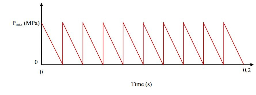
In modeling a structure under repeated impact loads (10 Pressure pulses at 10 steps)as below, I have a problem reading the results!
The problem is that logically, the structure's permanent deformation (at the center) should increase, But what I get doesn't fulfill this idea
Could anyone help me with this issue please?
PS. it's a transient structural analysis, my model has initial deformations as well as heat affected zone (reduced material characteristics) and welding residual stresses.
Materials are modeled as elastic-plastic (multilinear isotropic hardening), but I remember once one of the members told me to capture the material using Chaboche constants to get the hysteresis loop and read the permanent deformations, But the fact is that I couldn't find this constants for my material! (marine grade Aluminums)
Right now, I read the total deformations at the center of the panel. Could it be the cause of the problem? If so, what should I read instead?
November 23, 2020 at 4:51 ampeteroznewman
SubscribernYou will need to provide a lot more detailed information about your model to get advice on what to measure to evaluate the effect of the repeated loads.nCan you create a Project Archive .wbpz file and put that in a zip file to attach to your reply? That will let me take a closer look, but ANSYS staff are not permitted to download attachments, so insert images to explain a lot more about your model to get help from the ANSYS experts.nNovember 23, 2020 at 8:29 amelhamasadi
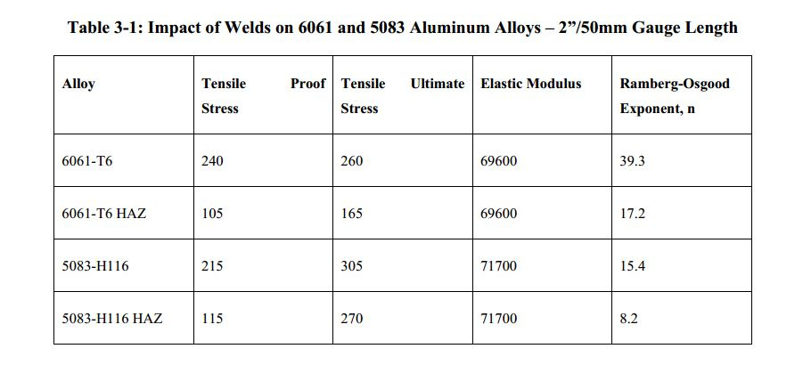
SubscribernHere's the project archive file. I want to calculate the exact value if nonlinear plastic strains (or deformations) occurred after each load.nArchive removed at user's request, RobnThe other information I've got is the chart below, about Ramberg-Osgood parameters. But I don't know how to use it. (Of course I have no idea if these information have anything to do with my problem)n n
November 24, 2020 at 12:18 am
n
November 24, 2020 at 12:18 ampeteroznewman
SubscribernIt helps if you say what version of ANSYS you are using. It is 2019 R3.nI opened your model, which is a Transient Structural model, and ran a few simple analyses to learn about the response of the structure to the applied loads.nFirst, I changed it to a 1-step analysis. In one system, I suppressed the Command object so there was only a pressure applied at t=0 of 0.11299 MPa which ramps down to 0 over 0.2 s. The pressure alone was insufficient to create any plastic strain.nIn another system I had only the Command object which created an initial strain in the part and suppressed the pressure load. The initial strain created a plastic strain of 0.001977 and that initial strain created a deformation of 0.378 mm. In the Transient analysis, this initial strain should be computed with Time Integration turned Off. There should be two steps with Time Integration turned off because after the displacement occurs over 0.1 s, that has defined an initial velocity. A second step that ends at 0.2 s is needed so that the initial velocity is zero at the beginning of step 3 when the pressure impact occurs.nI wonder if the dynamics of the 200 ms pressure hit is affecting the results. I changed the analysis to Static Structural, left the Command object to run in Step 1 at 0.1 s ramped the pressure up to 0.11299 MPa in Step 2 at 0.2 s and ramped it down to 0 in step 3 at 0.3 s. ramped the pressure on at 0.4 s and ramped the pressure down to 0 at 0.5 s and so in up to 0.9 s when four impacts have occurred. In the graph you can see plastic strain increasing after one impact, increasing slightly after the second impact and almost no extra after three impacts.n
 The maximum deformation is even flatter after the second impact.n
November 24, 2020 at 7:02 am
The maximum deformation is even flatter after the second impact.n
November 24, 2020 at 7:02 amelhamasadi
Subscribernyour suggestion to turn off the time integration option totally solved my problem.nThank you for your time and kind and generous explanations.nNovember 24, 2020 at 9:11 amRob
Forum Moderatorarchive removed. nNovember 24, 2020 at 11:46 amelhamasadi
SubscriberThank younApril 3, 2021 at 1:02 pmhamzasohailindia
SubscribernHi, I want to perform repeated impact test, nI saw that you also did the 10 impact. nI have given the velocity to hammer as 2.8m/s and done the simulation, it gives me only one impact, no matter how many steps I use, can you help me how I can do repeated impact,? PlsnnApril 3, 2021 at 8:12 pmpeteroznewman
SubscribernThere is no hammer. A Pressure load represents an impact force. The Pressure load has a time history as shown in the graph above. nApril 4, 2021 at 2:39 amhamzasohailindia
Subscriberif I have a velocity of 2.8m/s how can I convert it to pressure?? nApril 4, 2021 at 3:31 ampeteroznewman
SubscribernUse Physics.nWhat is the mass m of the hammer?nCalculate the kinetic energy (KE) that mass has when travelling at that velocitynKE = 0.5*m*v^2nWhat is the spring rate K of the beam?nCalculate the strain energy (SE) stored when the beam is deflected by a displacement xnSE = 0.5*K*x^2nAssume an equality SE = PE and solve for x. nCalculate the peak force F = K*xnWhat is the area A you want to use to apply the force?nPressure = F/AnThis is the simplest approach. You can make it more complicated and slightly more accurate.nViewing 10 reply threads- The topic ‘Why deformation decreases by increasing number of impacts?’ is closed to new replies.
Ansys Innovation SpaceTrending discussionsTop Contributors-
3492
-
1057
-
1051
-
965
-
942
Top Rated Tags© 2025 Copyright ANSYS, Inc. All rights reserved.
Ansys does not support the usage of unauthorized Ansys software. Please visit www.ansys.com to obtain an official distribution.
-


Ansys Assistant

Welcome to Ansys Assistant!
An AI-based virtual assistant for active Ansys Academic Customers. Please login using your university issued email address.
Hey there, you are quite inquisitive! You have hit your hourly question limit. Please retry after '10' minutes. For questions, please reach out to ansyslearn@ansys.com.
RETRY


