
TAGGED: dambreakflow, ls-dyna
-
-
October 28, 2020 at 2:51 am
MTLCY
SubscriberCould someone tell me why they build a SPH layer at the bottom?
October 28, 2020 at 12:46 pmpatjoy
SubscriberThe presence of downstream particles influences the wave profile, for dam-break waves there are typically two types of simulations, a dry-bed and a wet-bed simulation. Furthermore, this example is based on a SPH validation method termed a bore-in-a-box simulation, you can see the model domain and details in the paper they outline on the example page.nOctober 29, 2020 at 2:11 amSubscriberThank you very much for yor response. Another detail is that the bottom of the pillar is lower than the bottom rigid wall. Is it necessary?n nI modified this model by changing the shape of obstacle and size of the whole model, however, some unreasonable results occurs. Particles penetrated the obstacle and no interaction occurs(CONTACT_AUTOMATIC_NODES_TO_SURFACE is used to define the interaction between particles and FEM obstacle). Furthermore, particles moves upwards along the left wall. Could you tell me how to handle the penetration?n
 n
October 29, 2020 at 6:24 am
n
October 29, 2020 at 6:24 amIan Do
Ansys EmployeeMTLCY,nIt does not matter is the column sticks a little lower than the bottom surface. It is conservative to have it lower rather than higher.nnAs for contact, maybe you may first try with something like:n$---+----1----+----2----+----3----+----4----+----5----+----6----+----7----+----8n*CONTROL_TIMESTEPn$# dtinit tssfac isdo tslimt dt2ms lctm erode ms1stn 0.0 0.45 0 0.0 0.0 0 0 0n*CONTACT_AUTOMATIC_NODES_TO_SURFACE_MPP_IDn$# cid titlen 1SPH to Columnn$# ignore bucket lcbucket ns2track inititer parmax unused cparm8n 0 1 0 3 2 1.0005 0n$# ssid msid sstyp mstyp sboxid mboxid spr mprn 2 1 3 3 0 0 0 0n$# fs fd dc vc vdc penchk bt dtn 0.0 0.0 0.0 0.0 0.0 0 0.01.00000E20n$# sfs sfm sst mst sfst sfmt fsf vsfn 0.0 0.5 0.0 0.0 1.0 1.0 1.0 1.0n$# soft sofscl lcidab maxpar sbopt depth bsort frcfrqn 1 0.1 0 1.025 2.0 2 50 1n$---+----1----+----2----+----3----+----4----+----5----+----6----+----7----+----8nnElse, try these additionally, one at a time or combination:n- PENMAX=1000 in the option card B of *CONTACT_ keyword-n - XPENE=1000 in *CONTROL_CONTACT keywordn - try SOFT=1 and set SFS = SFM = 1.0e-12 in *CONTACT_AUTOMATIC_NODES_TO_SURFACE n - SOFSCL=1.0 (increase from 0.1 default if contact leaks, maybe for very high velocity impact or explosion) n nOctober 31, 2020 at 12:45 amSubscriberThank you so much for your kind suggestions. My issues have been addressed.nNovember 9, 2020 at 10:43 pmMiner
SubscriberHi all, I have a new issue in this simulation. After the water droped down, there are some particles move upwards along the left rigidwall. It is like those particles adhere to the wall. I have tried to reduce the gap between wall and water, but doesn't work. Could you help me to resolve this?n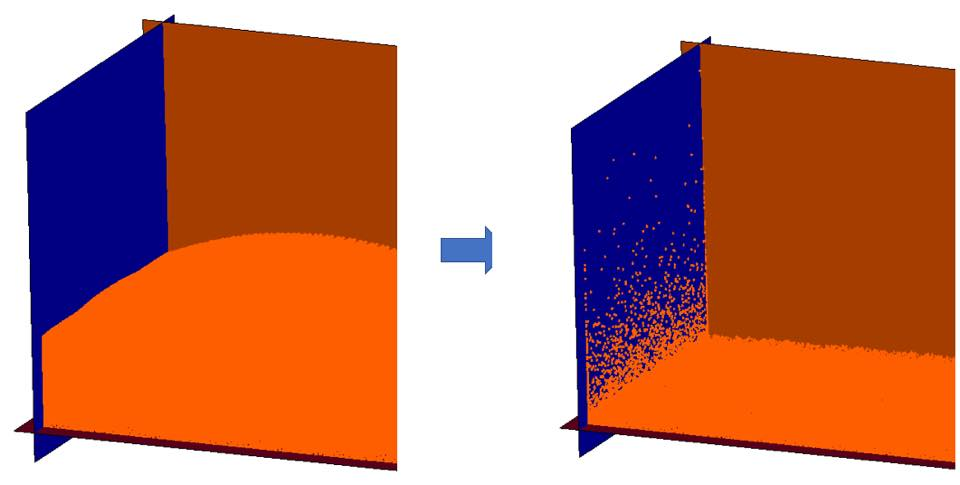 n
November 15, 2020 at 4:36 amSubscriber
n
November 15, 2020 at 4:36 amSubscriberHi all, I have a new issue in this simulation. After the water droped down, there are some particles move upwards along the left rigidwall. It is like those particles adhere to the wall. I have tried to reduce the gap between wall and water, but doesn't work. Could you help me to resolve this?https://us.v-cdn.net/6032193/uploads/AQFXOQNSY04K/image.png/forum/discussion/comment/96759#Comment_96759
The rigidwall must align the part surface. When change the particle spacing, small gap may generated between the rigidwall and part surface, thus the contact between rigidwall and part produced weird results. If particle spacing is changed, the rigidwall must be updated.nViewing 6 reply threads- The topic ‘Why build the SPH layer at the bottom?’ is closed to new replies.
Innovation Space Trending discussions
 Top Contributors
-
peteroznewman
 5734
5734 -
scabo
 1906
1906 -
Dennis Chen
 1419
1419 -
javat33489
 1305
1305 -
Shyam Prasad V Atri
1021
Top Rated Tags
© 2026 Copyright ANSYS, Inc. All rights reserved.
Ansys does not support the usage of unauthorized Ansys software. Please visit www.ansys.com to obtain an official distribution.
-


The Ansys Learning Forum is a public forum. You are prohibited from providing (i) information that is confidential to You, your employer, or any third party, (ii) Personal Data or individually identifiable health information, (iii) any information that is U.S. Government Classified, Controlled Unclassified Information, International Traffic in Arms Regulators (ITAR) or Export Administration Regulators (EAR) controlled or otherwise have been determined by the United States Government or by a foreign government to require protection against unauthorized disclosure for reasons of national security, or (iv) topics or information restricted by the People's Republic of China data protection and privacy laws.
