-
-
December 1, 2020 at 8:44 pm
hossein__mht
SubscriberHello
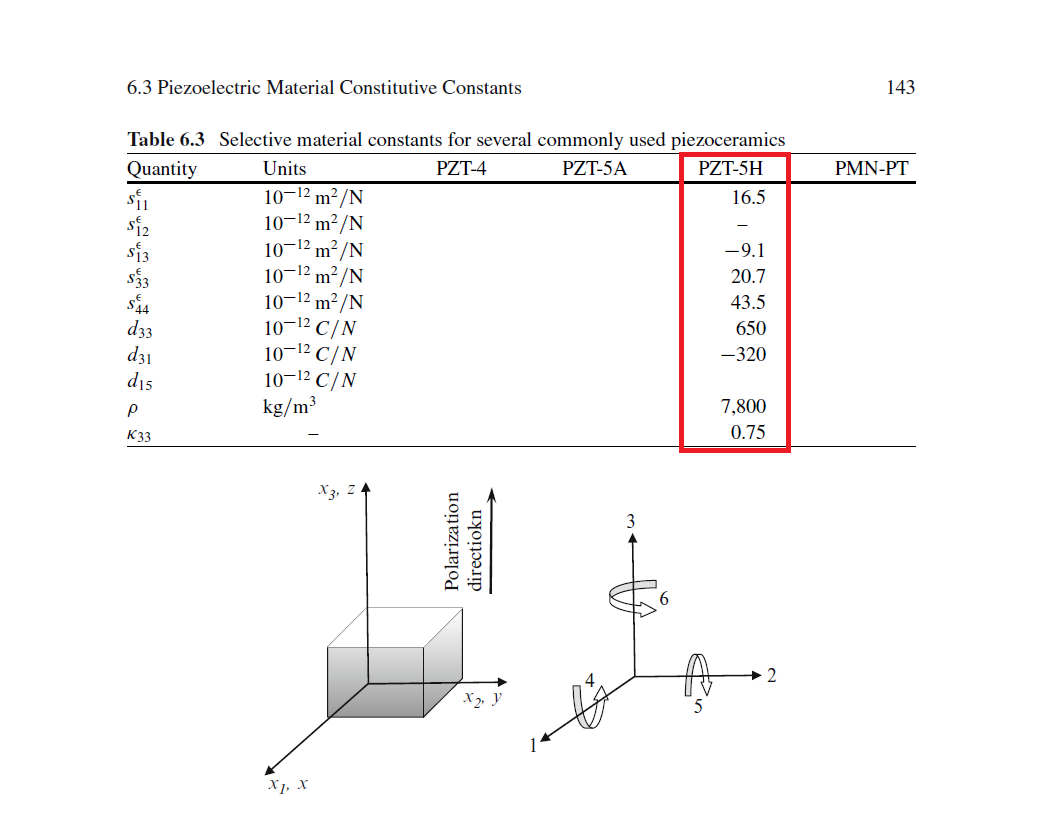
I've simulated a PZT-5H in ANSYS APDL. All the inputs of material properties are according to data sheet. The element type is SOLID226 and the KEYOPT(1) is 1001. The potential difference is 100 and 0 Volt in z direction and The permittivity in this simulation is at constant strain. The piezo should have 56 micro-meters if we apply these voltages but it has 0.064 micro-meters! I've written the session editor and uploaded some images of my simulation and the data sheet. Could anyone tell me the problem?
thanks a lot
Best regards; Mohammad Hossein Talebi
----------------------------------------------------------------------------------------------------
/PREP7
!*
ET,1,SOLID226,11
!*
KEYOPT,1,1,1001
KEYOPT,1,2,0
KEYOPT,1,4,0
KEYOPT,1,5,0
KEYOPT,1,6,0
KEYOPT,1,7,0
KEYOPT,1,8,0
KEYOPT,1,9,0
KEYOPT,1,10,0
KEYOPT,1,15,0
!*
!*
TB,ANEL,1,1,21,1
TBTEMP,0
TBDATA,,16.5e-12,,-9.1e-12,,,
TBDATA,,16.5e-12,-9.1e-12,,,,20.7e-12
TBDATA,,,,,43.5e-12,,
TBDATA,,43.5e-12,,33e-12,,,
MPTEMP,,,,,,,,
MPTEMP,1,0
MPDATA,DENS,1,,7800
MPTEMP,,,,,,,,
MPTEMP,1,0
MPDATA,PERX,1,,
MPDATA,PERY,1,,
MPDATA,PERZ,1,,1762.583881574612
TB,PIEZ,1,,,1
TBMODIF,1,1,
TBMODIF,1,2,
TBMODIF,1,3,-320e-12
TBMODIF,2,1,
TBMODIF,2,2,
TBMODIF,2,3,-320e-12
TBMODIF,3,1,
TBMODIF,3,2,
TBMODIF,3,3,650e-12
TBMODIF,4,1,
TBMODIF,4,2,
TBMODIF,4,3,
TBMODIF,5,1,
TBMODIF,5,2,
TBMODIF,5,3,
TBMODIF,6,1,
TBMODIF,6,2,
TBMODIF,6,3,
BLC4,-0.0025,-0.0025,0.005,0.005,0.036
! /VIEW,1,1,1,1
! /ANG,1
! /REP,FAST
! /DIST, 1 ,1.082226,1
! /REP,FAST
ESIZE,0.001,0,
MSHAPE,0,3D
MSHKEY,1
!*
CM,_Y,VOLU
VSEL, , , , 1
CM,_Y1,VOLU
CHKMSH,'VOLU'
CMSEL,S,_Y
!*
VMESH,_Y1
!*
CMDELE,_Y
CMDELE,_Y1
CMDELE,_Y2
!*
! /VIEW,1,1
! /ANG,1
! /REP,FAST
! /DIST, 1 ,1.082226,1
! /REP,FAST
! /DIST, 1 ,1.082226,1
! /REP,FAST
FLST,2,96,1,ORDE,2
FITEM,2,1
FITEM,2,-96
/UI,MESH,OFF
!*
/GO
D,P51X, , , , , ,UX,UY,UZ, , ,
FLST,2,96,1,ORDE,2
FITEM,2,1
FITEM,2,-96
/GO
!*
D,P51X,VOLT,100
FLST,2,96,1,ORDE,2
FITEM,2,97
FITEM,2,-192
/GO
!*
D,P51X,VOLT,0
! /VIEW,1,1,1,1
! /ANG,1
! /REP,FAST
! SAVE, 5h_loading,db,D:UniversityProjectCADPiezoapdl
! LGWRITE,'5h_loading','lgw','D:UniversityProjectCADPiezoapdl',COMMENT
! /VIEW,1,1
! /ANG,1
! /REP,FAST
FLST,4,96,1,ORDE,2
FITEM,4,1
FITEM,4,-96
CP,1,VOLT,P51X
FLST,4,96,1,ORDE,2
FITEM,4,97
FITEM,4,-192
! /VIEW,1,1,1,1
! /ANG,1
! /REP,FAST
! /DIST, 1 ,0.924021,1
! /REP,FAST
! /DIST, 1 ,0.924021,1
! /REP,FAST
! /DIST, 1 ,0.924021,1
! /REP,FAST
! /DIST, 1 ,1.082226,1
! /REP,FAST
! /DIST, 1 ,1.082226,1
! /REP,FAST
! /VIEW,1,1
! /ANG,1
! /REP,FAST
! /VIEW,1,1,1,1
! /ANG,1
! /REP,FAST
! /VIEW,1,1
! /ANG,1
! /REP,FAST
FLST,4,96,1,ORDE,2
FITEM,4,97
FITEM,4,-192
CP,2,VOLT,P51X
! /VIEW,1,1,1,1
! /ANG,1
! /REP,FAST
! /VIEW,1,1
! /ANG,1
! /REP,FAST
! /VIEW,1,1,1,1
! /ANG,1
! /REP,FAST
FINISH
December 2, 2020 at 1:17 pmErKo
Ansys EmployeeIf one takes say the properties for pzt5h say from here (you used a different form in ansys): https://www.globalspec.com/reference/48151/203279/appendix-2-electroelastic-material-constantsnnThen the displacement on applied voltage in a uniaxial bar/plate (dimensions: LxWxH) is given by:nAxial displ. = (Voltage applied)/(g33 * Elastic constant in axial dir)ng33 is about 0.017 for PZT5H, and E_axial ~ 11E10 Pa.nnUsing these values in the equation above gives an axial displacement of about 5.6E-8 m which is close to the Ansys results. So that is OKnnThank you and kind regardsnnEriknDecember 2, 2020 at 1:33 pmAnsys EmployeeHinIf we take the PZT5H (prefer working with these types of constants) from here: https://www.globalspec.com/reference/48151/203279/appendix-2-electroelastic-material-constantsnwe can then calculate the axial displacement in a uniaxial case for a bar.nnThe axial displ. is = (Voltage applied)/(g33*E_axial).nnFor pzt5h g33 ~ 0.017 (Vm/N) and E_axial ~11E10 Pa, giving a displ. of about 5.6E-8 m with a 100 V potential diff. across the bar/plate, which is what one would get with ansys.nnThank you and hope this helpsnnEriknnDecember 8, 2020 at 9:08 pmSubscriberDear Erik nThank you so much for your answer to my question. It helped me so much and I'm so grateful!nTo other people who are working on this subject, It's better to notice that the longitudinal displacement of longitudinal actuators is = (n)(d_33)(V)nn is the Number of stacked ceramic layers, d_33 is Longitudinal piezoelectric large-signal deformation coefficient [m/V], V is Operating voltage [V].nThis website may help you so much:nThanks and hope this helpsnBest regards, Mohammad Hossein TalebinDecember 9, 2020 at 11:03 amAnsys EmployeeMany thanks.EriknViewing 4 reply threads- The topic ‘Why aren’t the results of my simulation of PZT-5H correct?’ is closed to new replies.
Innovation Space Trending discussions
 Top Contributors
-
peteroznewman
 6249
6249 -
scabo
 1906
1906 -
Dennis Chen
 1457
1457 -
javat33489
 1308
1308 -
Shyam Prasad V Atri
1022
Top Rated Tags
© 2026 Copyright ANSYS, Inc. All rights reserved.
Ansys does not support the usage of unauthorized Ansys software. Please visit www.ansys.com to obtain an official distribution.
-
Ansys Assistant will be unavailable on the Learning Forum starting January 30. An upgraded version is coming soon. We apologize for any inconvenience and appreciate your patience. Stay tuned for updates.