We have an exciting announcement about badges coming in May 2025. Until then, we will temporarily stop issuing new badges for course completions and certifications. However, all completions will be recorded and fulfilled after May 2025.
Fluids

Fluids

Topics related to Fluent, CFX, Turbogrid and more.

Why am I getting an ever increasing value of Cp with the increase of TSR in VAWT simulation?

    • mmt
      Subscriber

      I am trying to get the bell-shaped Cp vs TSR graph in my 2D simulation of the H-Darrieus vertical axis wind turbine (using a sliding mesh model). However, I am always getting an ever increase of Cp value with the increase of TSR value i.e. the more I increase the value of the angular velocity of the sliding mesh, the higher the moment coefficient gets. What am I doing wrong and how can I get the bell-shaped curve?

    • Rob
      Forum Moderator
      Assuming it's set up and you're monitoring the correct value with the correct axis can you check it's not just that you've not reached the peak? Pictures will help.
    • mmt
      Subscriber
      Dear sir 
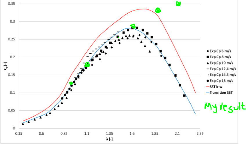
I am trying to replicate the results of a paper, so it's unlikely that the peak will be far-off. Here's a picture that shows the paper's results, experimental results, and my result. I am trying to get the transition SST model and according to the paper, it is run at inlet velocity 10m/s:

      This is what I have been doing:
      I have taken a very simple mesh. I have followed the tutorial of confluence (I replicated both the transient and steady parts. This is the link:https://confluence.cornell.edu/pages/viewpage.action?pageId=333371302)
      So far I have understood, to get the Cp vs TSR curve, I have to change the turbine's angular velocity here:
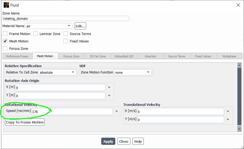
      This is run at 176 rev/min i.e. 18.4307 rad/s. For 10m/s inlet, the TSR will be (omega*turbine Radius)/freestream Velocity=(18.4307*1.125)/10=2.30.
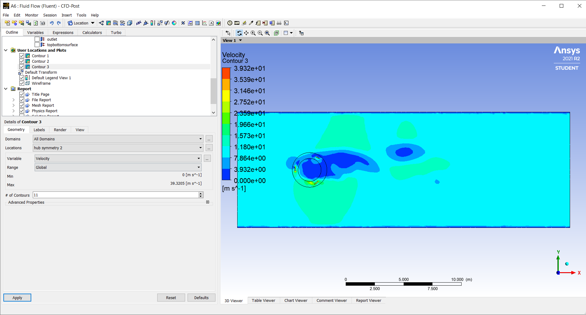
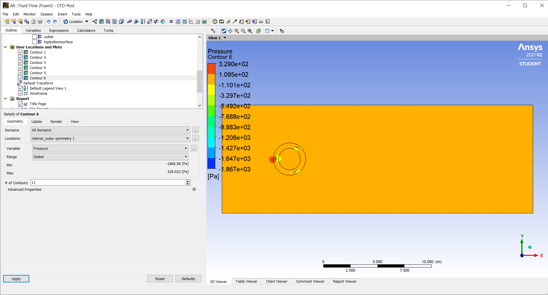
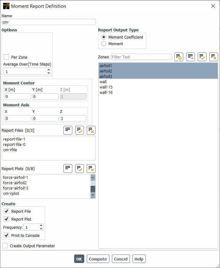
      This way, for each TSR point, I have to run the simulation and get the average moment coefficient value(Cm):
      Then, I calculated Cp=Cm*TSR. This way I calculated but always got an increasing value of Cp.
      Please let me know if I am making mistakes and how I can fix this.
      Thank you.
    • Rob
      Forum Moderator
      To confirm, the system spins anti-clockwise? Please post some contour plots.
    • mmt
      Subscriber
      Sir,
      Yes, it rotates anti-clockwise. I am posting the velocity contour here:
      Pressure contour:


    • Rob
      Forum Moderator
      Post process in Fluent and zoom in on the areas of interest. Looking at the image you have a local acceleration around the object: is the domain large enough to avoid channelling the flow through the VAWT?
    • mmt
      Subscriber
      Sir,
      I have made the geometry based on the paper, so I always assume that my geometry is okay. However, the radius of the ring circles was not provided, but the mentioned it is expected to be as narrow as possible and that is what I did. Should I bring any change to the geometry?
    • Rob
      Forum Moderator
      If the cell size isn't too dissimilar over the sliding interface then the position isn't too critical other than to avoid artificially squashing cells near the blades. The area of interest is the domain sides as there looks to be an acceleration caused by the VAWT blocking the flow.
      How did they define the blade shape in the paper?
    • mmt
      Subscriber
      Sir I'm not sure what you exactly mean by "define the blade shape". It's NACA 0015 airfoil. I am attaching the paper. I am working on rotor A as mentioned in the paper.
    • Rob
      Forum Moderator
      You have built the blade shape based on something, ie the paper. Is it the right shape, and have you resolved that shape (and wake) in the mesh?
    • mmt
      Subscriber
      Sir,
      Yes, I have drawn the shape based on the paper. I have taken the coordinates of NACA 0015 from NASA's website and my geometry is 2D.
    • Tarun mutyam Pichikala
      Subscriber


      Sir, I am doing analysis on Archimedes wind turbine in ansys fluent here my problem is torque is increasing with speed of the turbine because I’m not getting the that curve in cp vs tip speed ratio graph instead of that I am getting inclined line could please help me how to overcome this problem 


    • Rob
      Forum Moderator

      Have you defined the axis correctly? 

    • Tarun mutyam Pichikala
      Subscriber

      Yes, My turbine is rotating about x axis so I gave 1 0 0 to take moment about x axis. At orgin 

    • Tarun mutyam Pichikala
      Subscriber

      I am waiting for your reply sir 

    • Rob
      Forum Moderator

      If you keep increasing the wind speed and don't change the rotor speed to match why wouldn't the force increase. 

      As an aside, bumping a thread after 30minutes isn't going to speed up an answer. It is likely to annoy people. After a couple of days is fine, unless those days are weekend. 

    • Ahmed EISSA
      Subscriber

      dear mmt

      do you find any solution for this problem ?


      thankls in advance

    • mhm.luthfi
      Subscriber

      Hello, does anyone here get solution on this speed-torque trend issue? 


      Thank you


Viewing 17 reply threads
  • The topic ‘Why am I getting an ever increasing value of Cp with the increase of TSR in VAWT simulation?’ is closed to new replies.