-
-
February 20, 2023 at 9:46 am
-
March 1, 2023 at 8:43 am
Chinmay Telkikar
Forum ModeratorHello,
Please let us know what kind of simulation you are doing, what is the function of port1 and also some details on your model.
Thanks,
Chinmay -
March 1, 2023 at 9:39 am
Cedrick Biellmann
SubscriberHello,
I would like to evaluate the S parameters in the two ports in terminal mode and in modal mode
-
March 2, 2023 at 5:37 am
Chinmay Telkikar
Forum ModeratorHello,
Please share more details on the structure of the port1 to help us serve you better.
how did you connect port1 to the stripline and ground plane?
Is it a stub or wire bond?Thanks,
Chinmay -
March 2, 2023 at 1:46 pm
Cedrick Biellmann
SubscriberHello,
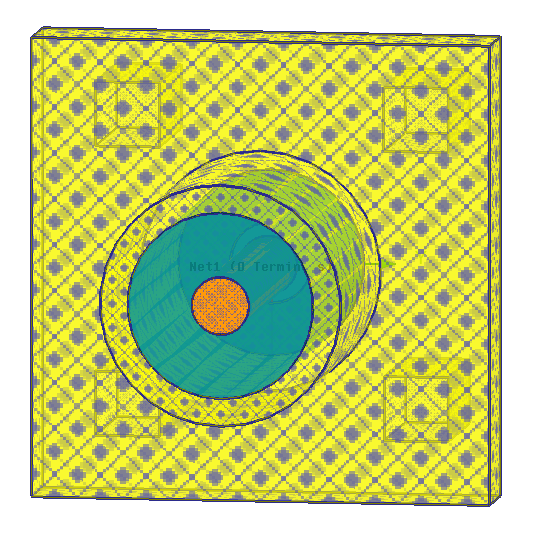
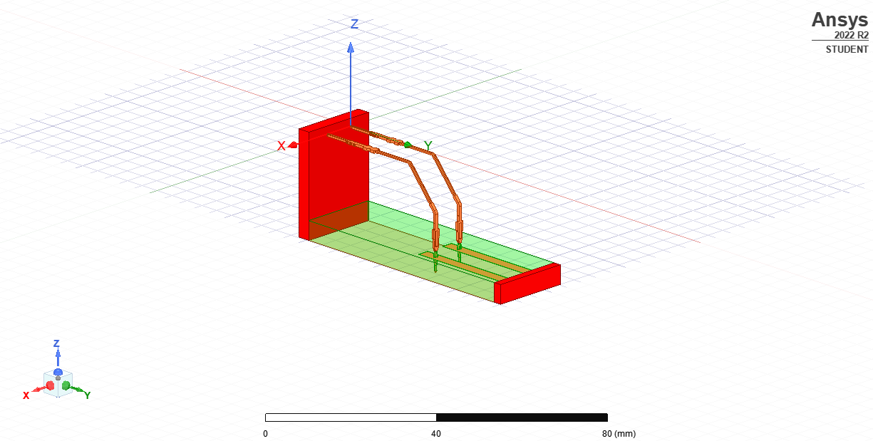
At below of the struture, there is a ground plane (in orange). After you have a dieletric FR4 with inside a copper strip line and a copper connetor. I have an input at the end of the strip lne in red and an output at the end of the connector. My problem is how to define the port 1? The port 2 can be realized with a wave port between the top of the strip line and the ground.
Thank you for your response.
CB
-
March 6, 2023 at 12:46 pm
Chinmay Telkikar
Forum ModeratorHello,
What is that green color object and how it is connected to the stripline and ground plane? Is it shorted with line and ground plane?Does this connector have one terminal (sIngle metal conductor) or two terminals? If it is a single metal conductor where is the return path?Thanks,
Chinmay -
March 6, 2023 at 1:31 pm
Cedrick Biellmann
SubscriberHello,
The green object is the dielectric (FR4). Below this object you have a ground plane and inside the dielectric a strip line linked to the connector. The connector is a single conductor and only the little surface at the end in red (see schematic) is plane. So how I can define a waveport or a lumped port at the end of the connector?
-
March 8, 2023 at 10:42 am
Chinmay Telkikar
Forum ModeratorHello,Why you are simulating this model with a connector? you can also use the same wave port at port1 as you created for port 2.If your connector has a single terminal, then where is the return path? The connector must have two terminals. One is for the forward path and another one is for the return path.Please refer to the SMA_RF_Jack 3D component available in the HFSS component libraries.The below screenshot shows the SMA connector which has two terminals:Thanks,Chinmay -
March 9, 2023 at 1:12 pm
-
March 23, 2023 at 9:22 am
Chinmay Telkikar
Forum ModeratorHello,
The connector must have two terminals and this is not the correct way of creating connector and assigning ports in Ansys HFSS.
Please answer the question which I already asked you in previous threads that why are you simulating this model using a connector?
You can use the same port2 representation at port1 and simulate a model.
Thanks,
Chinmay -
March 23, 2023 at 9:27 am
Cedrick Biellmann
SubscriberHello, thank you for your answer. The target is to modify the geometry of the connector (Put Hole inside for exemple) to see if there is modificatipon in s parameters. CB
-
March 24, 2023 at 1:57 pm
Chinmay Telkikar
Forum ModeratorHello,
It is hard to comment on your connector design and we need to look at your model for more details. Please submit a Service Request from Ansys Customer Portal to address your problem in a better way.
Thanks,
Chinmay
-
- The topic ‘Waveform port’ is closed to new replies.


-
3367
-
1050
-
1047
-
886
-
837

© 2025 Copyright ANSYS, Inc. All rights reserved.


