-
-
July 7, 2023 at 7:26 pm
mrijal
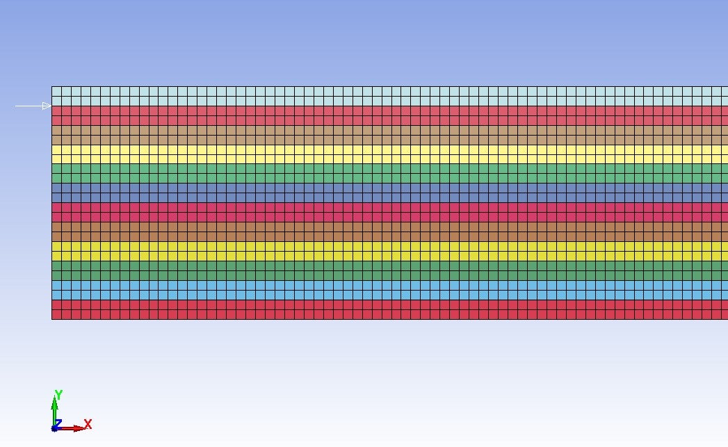
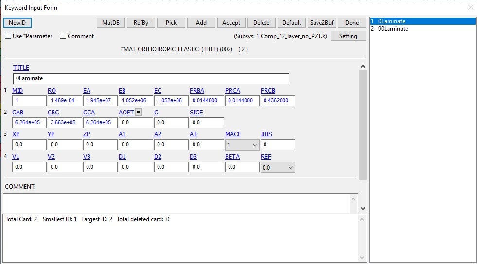
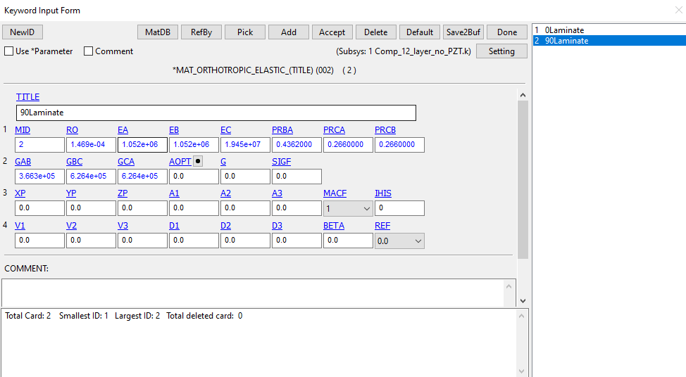
SubscriberI am modelling wave propagation in composites (cross-ply) using 2-D layered shell elements for each ply. I need to model cross-section of composite to ensure proper loading condition. As the normal direction ( material c- direction) of shell cannnot be changed I have to use transformation matrix to get material properties in the desired direction.The material properties can be seen in the figures. I am not sure if I am defining the model incorrectly or if my material properties is wrong but somehow, I am not getting expected results. And is there any simpler way to do it without using tranfromation matrix? I have tried all methods ( composite lay-up, defining stiffness matrix) but nothing seems to work. So any feedback would be highly appreciated.
Thanks
Manoz
-
July 10, 2023 at 4:19 pm
Jim Day
Ansys EmployeeWhich shell formulation (ELFORM in *SECTION_SHELL) are you using? If it's plane strain (shell ELFORM=13), you can instead model a single layer of 3D solid elements with nodal constraints in the thickness direction. There should then be no perceived restrictions on how you orient your orthotropic material directions. Apologies if I've misunderstood your situation. -
July 10, 2023 at 5:58 pm
mrijal
Subscriber@Jim Thanks for the reply. I am using ELFORM 13. The different color layer in the model pic specifies different plies. Do you mean to say I use a model with single solid element in z-drection as seen in the pic.? The properties that I am using also have Poisson's ratio > 0.5 in matrix dominated direction. I am also not sure if the solver accepts this value.
Manoz
-
July 10, 2023 at 6:14 pm
Jim Day
Ansys EmployeeYes, that's what I meant. If solids nodes are constrained in z, you'll get plane strain response. And yes, for an orthotropic material, Poisson's ratio can in some cases be > 0.5. The restrictions on elastic constants in an orthotropic elastic material are laid out in the LS-DYNA Theory Manual in the subsection "Constraints on Orthotropic Elastic Constants". -
July 12, 2023 at 4:06 pm
mrijal
Subscriber@Jim, Thanks for the feedback. I went through the theory manual and material properties defined for the model satifies all the stated condition. Does the thickness of the 3D solid element have to be large compared to other direction as that is the requirment for plane strain or is constraining the the model is z direction sufficient? Somehow I am getting different results for 3D solid elements when compared to 2D shell elements.
-
July 12, 2023 at 4:51 pm
Jim Day
Ansys EmployeeConstraining the z-translation is sufficient. This will prevent strain in the z-direction, hence you'll have plane strain. -
July 17, 2023 at 10:26 pm
mrijal
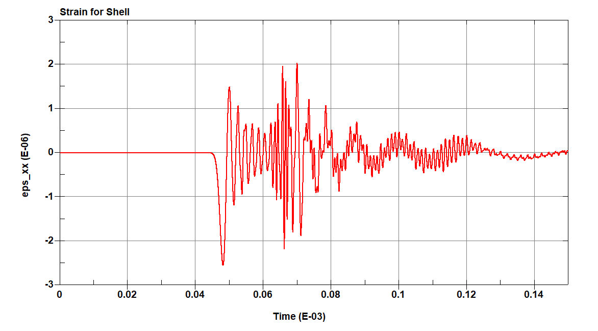
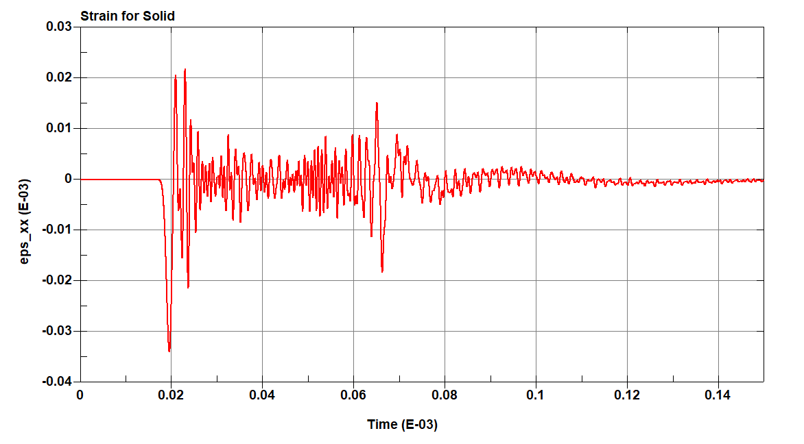
Subscriber@Jim I tried running models using 2D shell and 3D solid elements. But somehow I am getting different results in both cases. The time of arrival of waveforms and even the waveforms in each case is way too different. I have attached the waveforms at same location below. Based on the expected velocity,solid model seems to be working fine but I cannot figure out what's wrong with my 2D model. Any suggestions would be greatly useful.
-
July 17, 2023 at 11:05 pm
Jim Day
Ansys EmployeeYour original concern was whether the material orientation was defined correctly in the 2D Model and I suggested using a layer of 3D elements as a check. Orthotropic material orientation is more straightforward in 3D. It would seem your results confirm that the 2D model is incorrect. -
July 17, 2023 at 11:12 pm
Jim Day
Ansys EmployeeAs an experiment, change the *MAT_ORTHOTROPIC_ELASTIC input so the material properties in the 3 orthotropic directions (for example, EA, EB, and EC) are equal. This should constitute an isotropic material. If the 2D and 3D results are then in agreement, that almost certainly confirms your material directions are incorrect in the 2D model. I hope that makes sense. -
July 18, 2023 at 5:32 pm
mrijal
Subscriber@Jim.. Thanks for the feedback. You are right. I tried running both models using isotropic properties as you suggested. They behave the same. I have also run 3D solid model using tranformed properties ( using tranformation matrix which will have 2 materials card for 0 and 90 ply and applies to 2D shell model) and by defining different material direction for elemnts in 0 and 90 degree ply (only one material card). Both models also behave the same. I guess my orthotropic material orientation is some how wrong for 2D shell model. I had also created a post regarding this to which the link is attcahed below. My material orientation agress to direction as described in the post. Do you have any suggestions on confirming the material direction for the 2D shell element?
/forum/forums/topic/element-direction-in-ls-prepost/
Thanks,
Manoj
-
- The topic ‘Wave propagation in composites’ is closed to new replies.


-
2979
-
970
-
857
-
750
-
599

© 2025 Copyright ANSYS, Inc. All rights reserved.

