Hello,
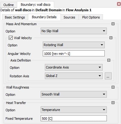
I am simulating a simple model of a brake rotor to check the wall velocity configuration. The model is only a stationary fluid domain. I attach a picture of the model, the rotor wall boundary and the wall velocity setup.
I have read the following about wall velocity:
"This option applies to both stationary and rotating domains and enables the wall to rotate with a specified angular velocity. The angular velocity is always in relation to the local (relative) frame of reference (that is, relative to the rotating frame in a rotating domain). An axis must be specified in a stationary domain and can optionally be specified in a rotating domain. Axis specification follows the same rules as for cylindrical velocity component inlets."
However, the following mistake message appear when I run the simulation:
ERROR #002100080 has occurred in subroutine CHECK_NORMV.
Message:
The specified velocity vector on the boundary patch
wall disco
has a significant normal component at one or more faces. One of
these face locations is
(x,y,z) = ( 2.21063E-02,-2.78752E-02, 2.33333E-03).
The angle between the specified velocity and the element surface is 87.597 degrees at this face. This is considered an error because
it implies that the mesh is moving. The following are possible
Reasons for the error message:
1. There is a setup error; for example, an incorrect axis of rotation.
2. There may be a meshing problem; for example, the nodes on a rotating surface might not lie on the surface of revolution.
3. The boundary is curved and the mesh is very coarse. In this case, you may modify the tolerance by increasing the expert parameter 'tangential vector tolerance wall' from its default of 20 degrees.
I have checked the mesh and the axis of rotation but I can't solve it.
Thanks.