TAGGED: Implicit-VOF, multifluid-vof, transient, vof
-
-
October 23, 2023 at 7:35 am
abdullahhassan
SubscriberDear Sir,
I am new to ANSYS and doing an Implicit VOF transient simulation on single tube parrallel heat exchanger.
Viscous Model:
K-Epsilon with realizable and Enhanced wall function
VOF Model:
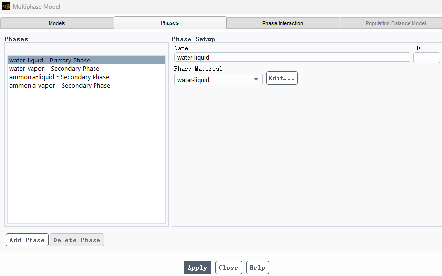
Primary phase = water liquid (as I don’t need it to put in boundry condition volume fraction)
Secondary phases = water vapor, ammonia liquid, ammonia vapor.
Material:
Tube side = Hot fluid =water that converts from vapor to liquid with VOF Lee’s Model at frequency 180/s.
Shell side = Cold fluid = ammonia that converts from liquid to water with Lee’s model frequency 89/s.
Boundry conditions:
Velocity inlet and pressure outlet.
Tube side = I put water vapor Volume fraction = 1
Shell side = I put ammonia liquid volume fraction = 1
Method:
Piso Scheme with all second order upwind
Control:
Initially all are at 1 UR factor and then reduced the convergence UR till 0.7.
Initialization:
Hybrid.
Patch:
Water vapor VF = 1 in tube domain
Ammonia liquid VF = 1 in shell domain.
Problem:
I am facing two big issues.
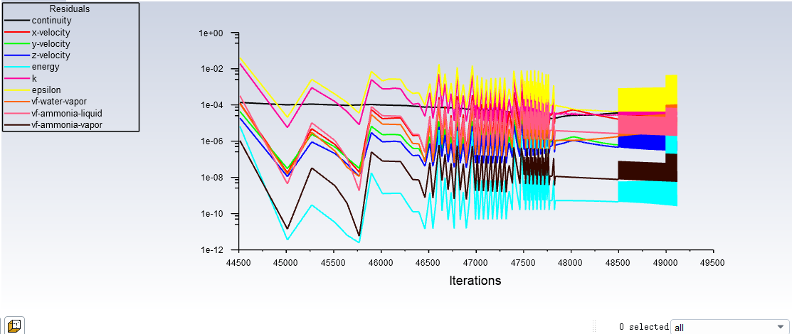
1- Continity residual is showing a straight line. It is not converging to 1e-3 or 1e-4. it stays at 1e-1 as a straight line. All other residuals are below 1e-6.
2- As water liquid is primary phase so I can’t assign it to any domain. I did the patch to avoid any water liquid in shell domain. After the simulation. What I find out through volume fraction surface and volume intergrals is that “the water liquid is present in both the tube and shell domain”. In tube domain it is condensed from water vapor but from where it comes to shell domain.
Can you guide me on this?
-
October 24, 2023 at 11:45 am
abdullahhassan
SubscriberHello, Can you please suggest me some solution????? -
October 24, 2023 at 4:05 pm
Rob
Forum ModeratorI suspect you need two phases, one for the liquid and a second for gas. Each is a mixture. You then need to transfer ammonia and water from/to their respective phases.
-
October 25, 2023 at 2:23 am
abdullahhassan
SubscriberYes,
I have chosen four phases.
And in boundary conditions, from phases, I assign Water Vapor volume fraction =1 to Tube inlet,
Ammonia liquid volume fraction = 1 to Shell Inlet. and then after initialization,
I patch the water vapor VF = 1 at tube domain and Ammonia liquid VF =1 at shell domain.
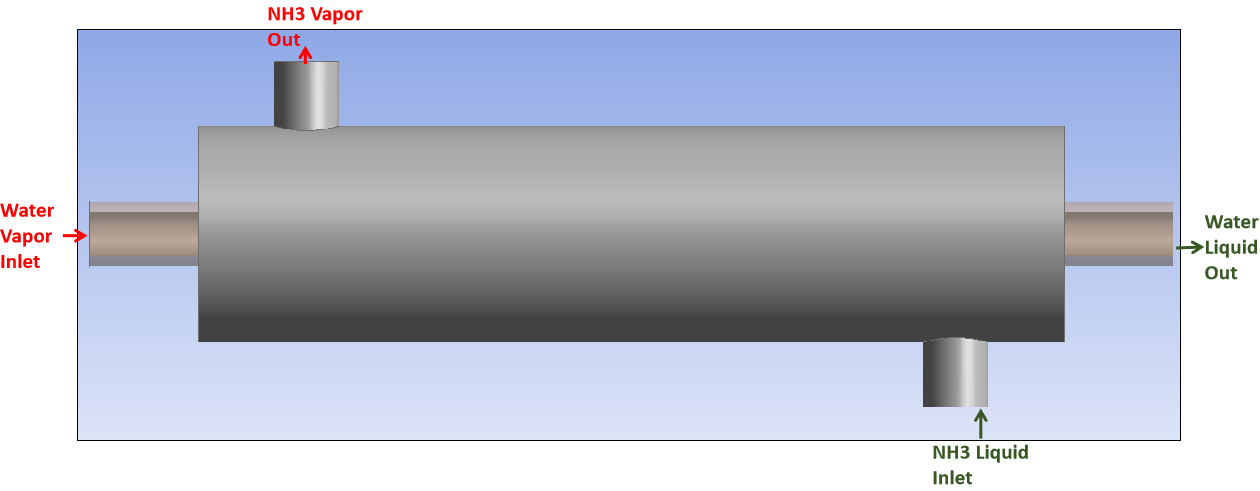
Above is the geometry.
And if you want to see the traces of water liquid, please refer below image.
-
October 25, 2023 at 8:33 am
Rob
Forum ModeratorDid you set all of the boundary conditions, including outlet and patch the zones?
-
October 26, 2023 at 2:38 am
abdullahhassan
SubscriberYes, I have put an outlet guage pressure = -0.15
and patch volume fraction of ammonia liquid = 1 in Shell domain.
and patch volume fraction of water vapor = 1 in tube domain.
-
October 26, 2023 at 10:33 am
Rob
Forum ModeratorAssuming all bc's are set correctly, if convergence is initially poor you could be getting some of the wrong material in the channel.
-
December 2, 2023 at 5:29 am
abdullahhassan
SubscriberSo, how to resolve it?
if you see below image, every residual went below 1e-3 but the continuity is stable at 1e-1.
Initially, i started with Under Relaxation Factors of 1 in the momentum, physics and VF in control tab. but after 100 iterations, I changed it to 0.7 or 0.8 to reduce the continuity. but still the continuity reduces to a little but remains in 1e-1.
Can you guide me how to resolve it.
-
December 2, 2023 at 7:57 am
abdullahhassan
SubscriberCan you help me in this?
How to restrict a primary phase in one domain and restrict it to enter into another domain. ?
-
December 4, 2023 at 1:02 am
abdullahhassan
SubscriberHello, can you please guide me on this matter.
-
December 5, 2023 at 10:08 am
Rob
Forum ModeratorPlease remember that we don't work weekends, and may not be in the same time zone as you are. How much mass is in the wrong place? With two separate channels & phase change convergence issues could easily result in the wrong species being seen. Another option is to use system coupling to link two separate CFD models.
I also dislike using VOF for phase change at present.
-
December 19, 2023 at 6:48 am
abdullahhassan
Subscriber -
December 19, 2023 at 7:17 am
abdullahhassan
SubscriberThank you Rob for your reply.
I have tried to change the settings and did the simulation again but it also doesn't work.
The complete data is mentioned below.
The setup is EVAPORATION (Shell) - CONDENSATION (Tube) in heat exchanger.
It is an Implicit MIXTURE transient simulation on a single-tube heat exchanger.
Viscous Model:
K-Epsilon with realizable and Enhanced wall function
Mixture Model:
Primary phase = R134a Vapor (as I don’t need it to put in boundary condition volume fraction)
Secondary phases = R134a Liquid, NH3 Liquid, NH3 Vapor.
Material:
Tube side = Hot fluid =NH3 that converts from VAPOR to LIQUID with Lee’s Model at a frequency of 180/s.
Shell side = Cold fluid = R134a that converts from LIQUID to VAPOR with the model at a frequency of 89/s.
Boundry conditions:
Velocity inlet and pressure outlet.
Tube side = I put NH3 Vapor Volume fraction = 1
Shell side = I put R134a Liquid volume fraction = 1
Method:
Piso Scheme with all second-order upwind
Control:
Initially, all are at 1 UR factor and then reduced the convergence UR to 0.7.
Initialization:
Hybrid.
Patch:
NH3 VAPOR VF = 1 in the tube domain
R134a LIQUID VF = 1 in shell domain.
Problem:
Still, the issue persists.
1- Continuity residual shows a straight line.
2- As R134a VAPOR is the primary phase I can’t assign it to any domain. I did the patch to avoid any R134a VAPOR in the shell domain. After the simulation. I found out through volume fraction surface and volume integrals that “the R134a VAPOR is present in both the tube and shell domain”. In the shell domain, it is evaporated from R134a LIQUID but from where it comes to the shell domain.
If you see the blue highlighted circles. It shows that R134a Vapor is in a Cold Outlet as well as a Hot Outlet.
Also, if you see the yellow highlighted figures. The volume fraction for Cold Outlet should be 1 but is equals to around 1.38.
In my understanding, all the issues are associated with the inability to assign a Primary Phase to any specific domain.
Can you please guide me on this?
-
December 19, 2023 at 7:21 am
abdullahhassan
SubscriberAlso, Can you guide me on this as well?
"Another option is to use system coupling to link two separate CFD models"
How to use system coupling?
-
December 19, 2023 at 11:04 am
Rob
Forum ModeratorA mass flow of 1.9e-10 kg/s relative to around 0.91 kg/s is likely to be numerical, and I'd check the flow, energy balance etc to see if it's actually a problem.
Two models via system coupling is something on my to-learn list. For now, please check the Learning and Documentation for more details.
-
December 19, 2023 at 3:37 pm
abdullahhassan
SubscriberDear Rob,
The point is. this is the first calculation in which the volume fraction is very low in the opposite domain. but previously, I have a number of simulations and in those simulations, it is showing a big value in both the domains.
Now please guide me on what should I show you so you can check the problem.
Is it possible to bind the primary phase to any domain? by ANSYS interface, it is not possible. but is there any other possibility?
-
December 19, 2023 at 5:09 pm
Rob
Forum ModeratorFluent is designed for single domain systems, ie one fluid zone. Whilst you can run two (or more) separate zones this can get a little complicated, and adding phase change won't help, as you're seeing. In your case you have a multiphase system, so can only set boundary conditions and patch materials into the cell zones, plus set the phase change materials. If the solver is struggling to converge you may find small amounts of the wrong material to be added to a zone: you can't avoid this, other than to ensure very good convergence.
-
December 20, 2023 at 9:08 am
abdullahhassan
SubscriberDid it mean, ANSYS will struggle to give appropriate results with a multiphase (Condensation + Evaporation) system?
Do you think that dividing the domains into different regions and defining these regions with phases is a possible solution? Someone told me this but I don't know how to do it.
What do you think on this?
-
December 21, 2023 at 12:05 pm
Rob
Forum ModeratorNo, Fluent is fine with phase change if it's done correctly. Two separate domains just complicates matters, and if the solver has a mass balance issue you may find the "wrong" material in the "other" domain.
Having two separate models and passing thermal data will remove the issue as there aren't any additional materials to be used in the mass balance stage. I've not used the Fluent-Fluent system coupling, hence you'll need to do some reading and potentially ask in another topic/thread.
-
- The topic ‘VOF Issue’ is closed to new replies.


-
3407
-
1057
-
1051
-
896
-
887

© 2025 Copyright ANSYS, Inc. All rights reserved.


