TAGGED: #fluent-#cfd-#ansys, fluent, pbm
-
-
May 8, 2024 at 8:39 am
zj X
SubscriberHello, everyone!
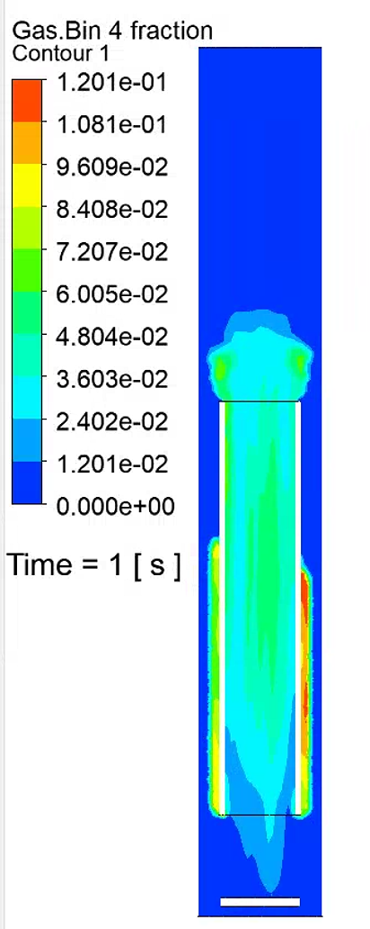
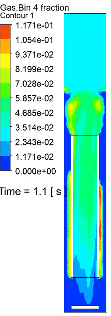
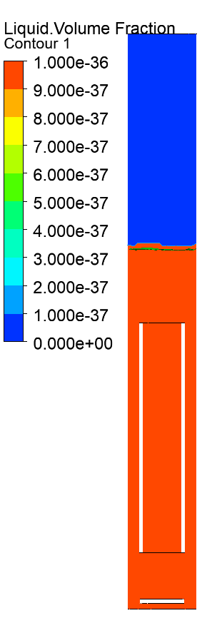
I am simulating gas-liquid-solid three-phase mass transfer. Also I want to simulate the aggregation and breakage of bubbles, but I am distressed with the fact that after adding the PBM model I find that there is a bubble particle size distribution and liquid velocity above the liquid surface yet I can't monitor the liquid phase volume fraction.
Now, I'm not sure what is wrong. All I know is that the above problem occurs when I use PBM model. I have tried using udf to suppress the liquid velocity above the liquid level but it doesn't help. I have also tried modifying the mesh and using higher order discretization to reduce numerical diffusion but that didn't help either.
So the question is how to avoid having liquid velocity and bubble particle size distribution above the liquid surface when using PBM
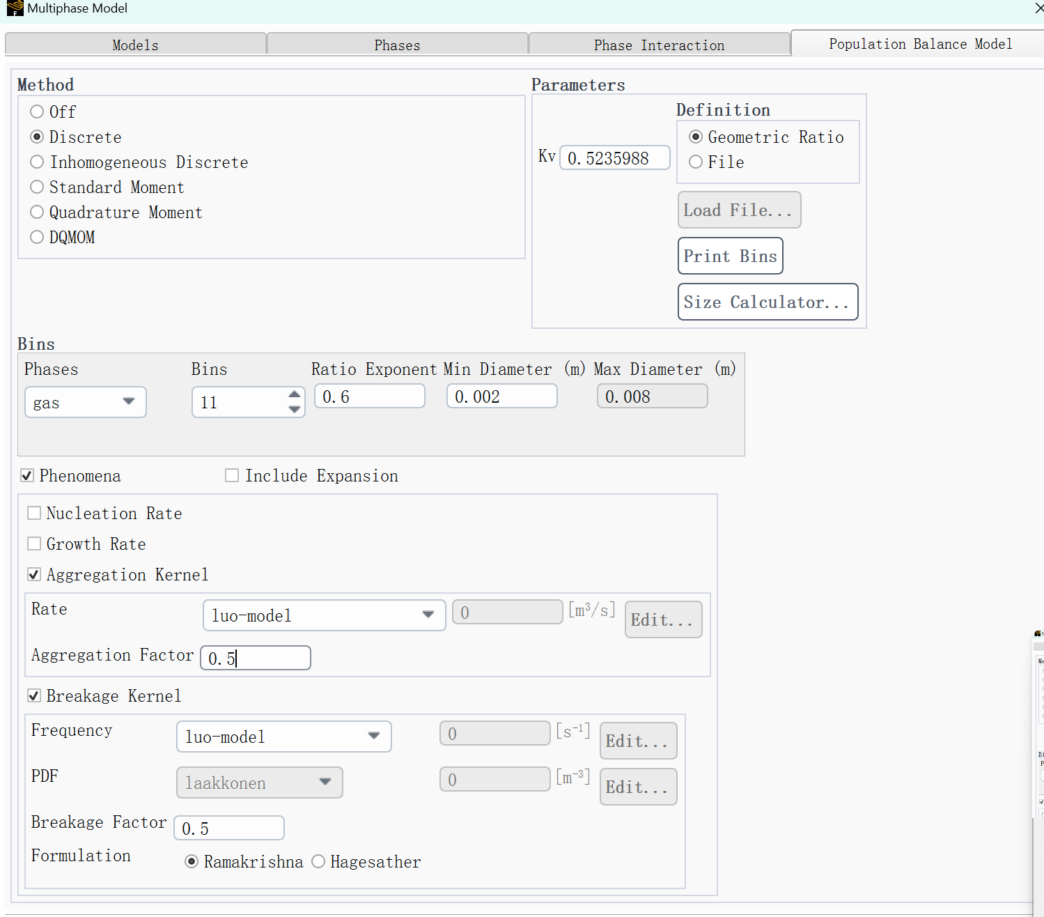
Here is the specific setup for my simulation: an Eulerian multiphase flow model with a mixture of gas-liquid-solid phases, with a liquid phase (water + liquid toluene) in the primary phase, and gas (air + gaseous toluene) and solid phases (silicon + liquid toluene) in the secondary phase, with gas-liquid, gas-solid, and liquid-solid mass transfer.Before the simulation, I patch a part of the area above the model with a gas phase volume fraction of 1.
Thanks in advance for your patience. -
May 8, 2024 at 10:35 am
Rob
Forum ModeratorWhat is the liquid volume fraction in the head space?
-
May 8, 2024 at 10:51 am
-
-
May 8, 2024 at 12:58 pm
Rob
Forum ModeratorThere will be a tiny amount, and that's why you're seeing a velocity result.
-
May 9, 2024 at 1:43 am
zj X
Subscriber
-
-
May 9, 2024 at 8:48 am
Rob
Forum ModeratorIt's unlikely that you'll get zero liquid in the head space, and it's that tiny volume fraction that gives the velocity field you're seeing. One trick is to use a Custom Field Function (in the User Defined tab) of vol_frac_liquid x velocity as that'll mostly eliminate the odd result. Clip planes are another option.
-
May 9, 2024 at 12:20 pm
zj X
SubscriberThanks for your replying.I will try Custom Field Function.
And is there a solution to the bubble bin fraction in the head space?
I write an udf to make the aggregation rate only below the liquid surface by limiting the height, but it didn't help.There are still bubble bin fraction above the liquid surface.
I can give more information if you need.

-
-
May 9, 2024 at 12:28 pm
Rob
Forum ModeratorThe bubble size will be determined by the PBM model, so what in the model will switch over to putting all of the gas into the largest bin size?
-
May 9, 2024 at 1:13 pm
zj X
SubscriberI use default luo aggregation model and luo breakage model to simulate bubble aggregation and breakage.
When the gas does not reach the liquid surface, there is no bin size in the headspace, but when the gas breaks through the liquid surface, bin size appears in the headspace.
It looks like the gas is aggregating and breaking in the headspace, which doesn't make sense.
The bottom is the velocity-inlet for the gas. The gas rises from the bottom to the outlet.Pressure-outlet at the top,all bin fraction‘s boundary value is 0,is there mistakes in my settings?
Thanks for your patience.

-
-
May 9, 2024 at 1:20 pm
Rob
Forum ModeratorWhy doesn't it make sense? The PBM set up has a trigger to break & form bubbles, and the Eulerian model has a size associated with the second phases.
-
May 9, 2024 at 1:49 pm
zj X
SubscriberSo I get all normal results.
Thanks for all your replies Mr. Rob.
-
-
- The topic ‘Unusual liquid velocity and bubble size distribution by using PBM’ is closed to new replies.


-
3402
-
1052
-
1051
-
896
-
877

© 2025 Copyright ANSYS, Inc. All rights reserved.


