We have an exciting announcement about badges coming in May 2025. Until then, we will temporarily stop issuing new badges for course completions and certifications. However, all completions will be recorded and fulfilled after May 2025.
Fluids

Fluids

Topics related to Fluent, CFX, Turbogrid and more.

Unphysical results

    • thomasrappaport
      Subscriber

      Hi everyone,

      I’m a PhD student working on the diffusion of particles near a boat. Before I can study particle diffusion, I need to fully understand the flow topology around the ship. I’m currently performing a mesh independence study, but I’m encountering some issues with non-physical velocity values in front of the boat (see attached image).

      Here are the details of my setup:

      • Flow Conditions:

        • Inlet: Uniform velocity profile with U∞ = 5 m/s
        • Top and Side Boundaries: Symmetry
        • Bottom: A moving wall (moving in the same direction and at the same speed as the inlet velocity)
        • Outlet: Pressure outlet with gauge pressure = 0
      • Solver and Discretization:

        • Turbulence Model: k-ω SST
        • Solver: Coupled
        • Discretization Schemes: All set to 2nd order
        • Convergence: Residuals decrease by approximately 4 orders of magnitude, which seems acceptable. However, global flow parameters (such as the drag coefficient and wall shear stress) oscillate around an average value and never fully settle.
      • Mesh Details:

        • Mesh Type: Polyhedral
        • Number of Cells: Approximately 15 million
        • Boundary Layer: 15 inflation layers with the first layer height set to 3.5 mm

      It appears that the highest velocities are observed near the walls and in regions with corners or high curvature. I have also tried enabling the corner correction option; however, I couldn’t find clear recommendations regarding the value of the associated constant, and it seems that the correction did not change the results significantly.

      My question is:
      What guidelines or recommendations can be provided to address the oscillatory convergence and the presence of non-physical velocities, particularly in these high-curvature or corner regions? Any advice on adjustments to the mesh, solver settings, or boundary conditions would be greatly appreciated.


      Thank you!

    • Rob
      Forum Moderator

      Why would particles diffuse? Can you plot some contours on planar surfaces to show what's going on with the flow? 

    • thomasrappaport
      Subscriber

      Hi rob thanks for the reply.

      I’d like to clarify a mistake in my previous post—I mistakenly mentioned "particle diffusion" when I actually meant "particle dispersion." My PhD work is focused on simulating the dispersion of particles on and around the boat to create a concentration map. However, before introducing particles into the simulation, it’s crucial to first understand the flow topology around the boat.

      What kind of contour do you have in mind ? Velocity Magnitude, Pressure, TKE ? 

      Thanks for the help

    • Rob
      Forum Moderator

      OK, thanks, that makes more sense.  Velocity magnitude would be good. Pressure on the hull may also be useful as you're looking for separation effects. 

    • thomasrappaport
      Subscriber

      Okay here are some contours : 

      Pressure coefficient on the bow part :

      Velocity around the ship :


      If you need anything else please feel free to ask.


    • Rob
      Forum Moderator

      That looks OK, if you replot with node values off you can judge if the mesh is fine enough in the regions of high gradients. 

      For oscillating results use residuals to check bulk convergence and point monitors to understand the fluctuations and whether they're significant. 

    • thomasrappaport
      Subscriber

      What I'm truly questionning as I said in my first post are the physical values. My velocity inlet speed is 5 m/s, and I've a maximum speed that can go up to 9.72 m/s, so almost double. I don't see any reasons for such acceleration. In the litterature i've seen acceleration of 30% but not above. If I look at my y+ it varies between 0.164 and 183, I've read in the RANS Turbulence Modeling Best practice 2019 of F.Menter that k-w SST is insensitive to y+. I was wondering if that's really true ? It seems that problematic zones (with high speed) are corner near the bow and have y+ that range from 40 to 60


    • Rob
      Forum Moderator

      You've also not plotted to show if the result is a mesh effect, contour smoothing or an overly constrained flow. How much space is there around the hull, and what is the % blockage factor of the boat onto the inlet? Look for "Projected Area".

      Separately k-w does need a well resolved near wall mesh to benefit from the various schemes, otherwise k-e with Enhanced Wall Treatment is an option. y+ just means the cell next to the wall is at a height to capture stuff, it's also easy to monitor so everyone gets fixated on that value: how deep the inflation layer is, cell aspect ratio and cell growth rate are also very important but not necessarily as easy to check with a single number. 

    • thomasrappaport
      Subscriber

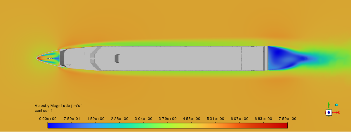
      The blockage factor is 0.076%, calculated using the boat’s projected frontal area of 60.1471 m² relative to a domain measuring 540 m in width and 145 m in height. Since the boat is centered, there is approximately 210 m of clearance on each side of the domain.

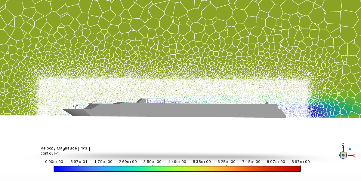
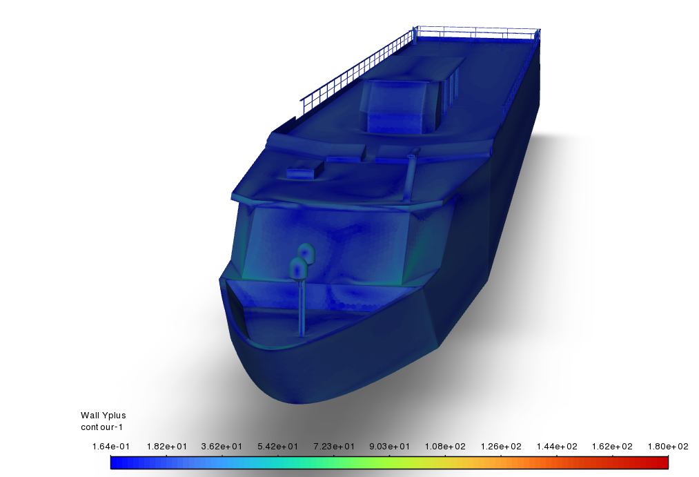
      For the inflation layers, I have implemented 15 layers, with the first layer set at a height of 3.5 mm. Regarding the mesh quality, the minimum orthogonal quality is 0.1, the average is 0.87, and the maximum is 1. The aspect ratio ranges from a minimum of 1.32 to an average of 8.1, with a maximum of 257.28.

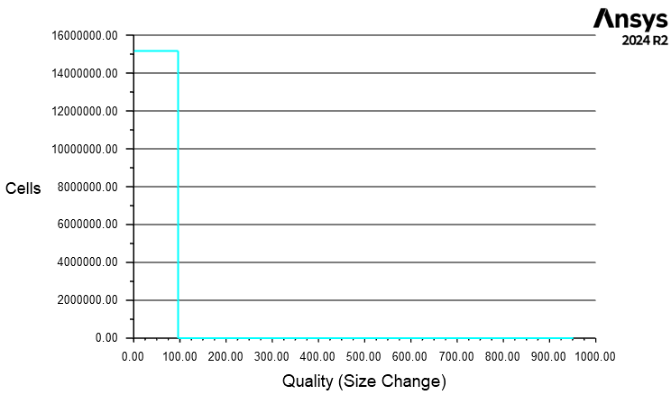
      Concerning the cell growth rate, I’m not entirely sure how to interpret the size change metric, but the values are as follows: a minimum of 1.08, an average of 2.3, and a maximum of 951.283.


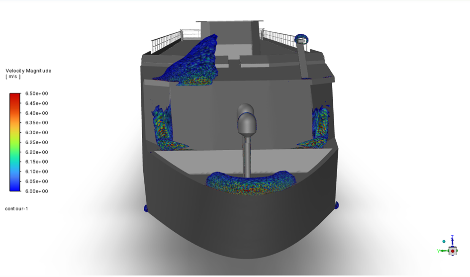
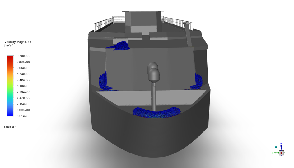
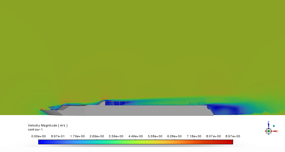
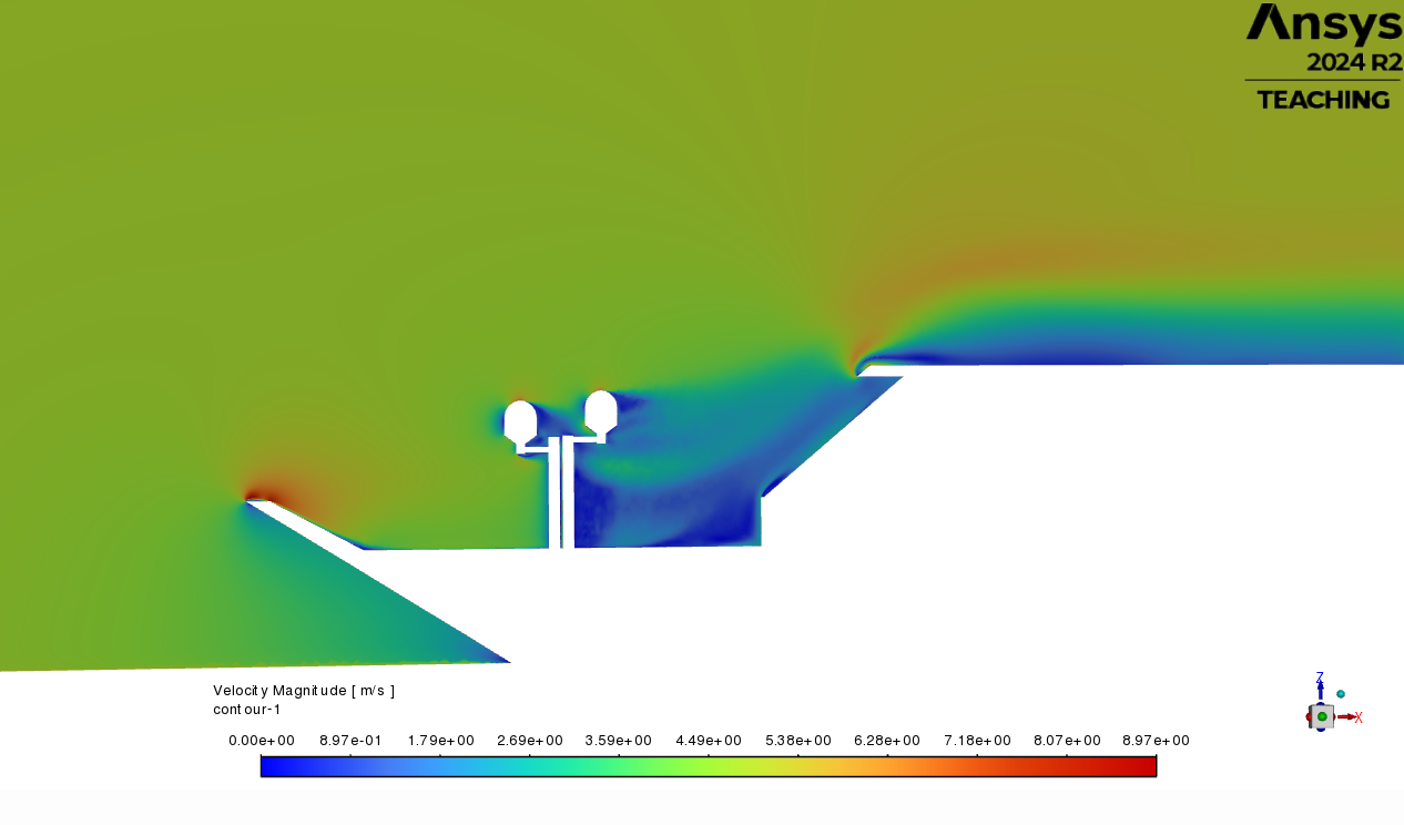
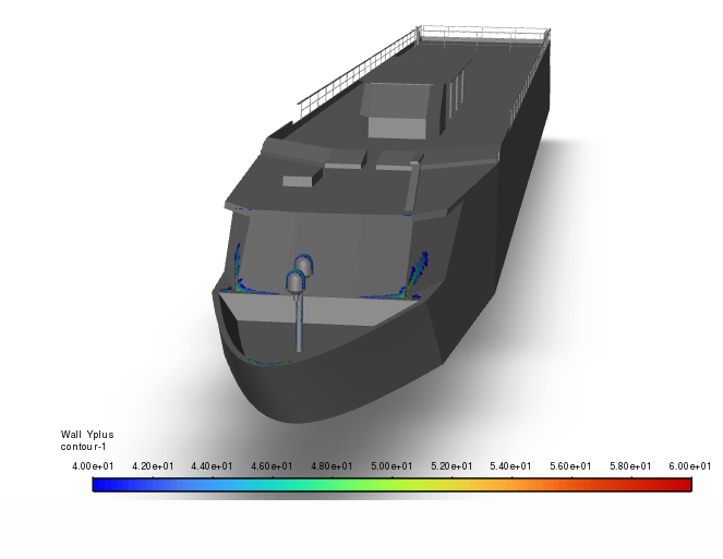
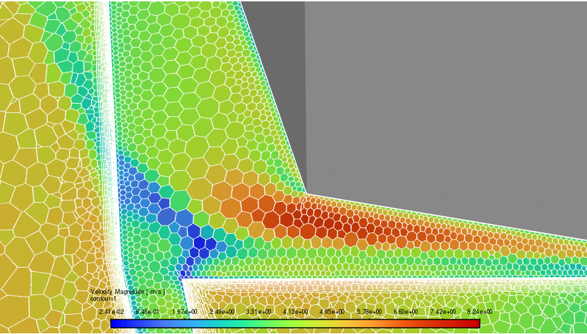
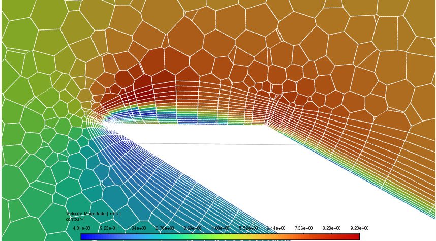
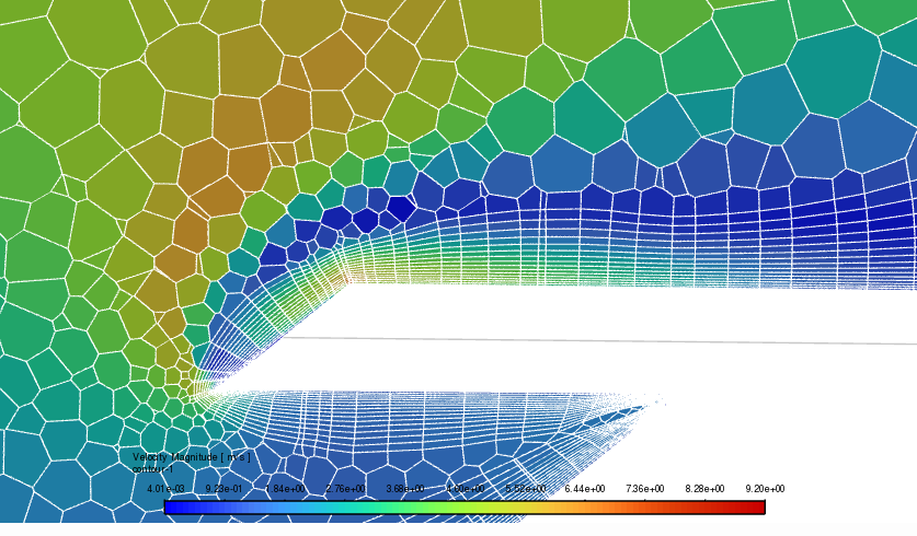
      For the contour  on the problematic zones : 


      Out of curiosity, if SST k-w still needs a good resolution, why is there an "insensitive y+ wall treatment" for k-w models ?

      Thanks for any help given :)

    • Rob
      Forum Moderator

      I think the y+ insensitive bit is similar to Enhanced Wall Treatment - in that if the mesh is sufficient one option is used, if it's not another is used. It'll be explained properly in the manual: as I typically cover multiphase y+ is less of a concern! 

      The flow looks sensible but have a think about how cell aspect ratio might effect the recirculation and separation effects. 

    • thomasrappaport
      Subscriber

      So if I understand correctly my maximum aspect ratio is too high ? What value should be sufficient ?

    • Rob
      Forum Moderator

      It's possibly too high. When flow is aligned with a surface inflation is an efficient way of resolving near wall gradients. When flow separates inflation meshing is just a load of high aspect ratio cells. Check the various guides for advice. 

Viewing 11 reply threads
  • You must be logged in to reply to this topic.