TAGGED: ansysmaxwell, maxwell, maxwell-2d, maxwell3d, synchronous-generator
-
-
July 11, 2021 at 7:36 am
ranjanpal999
SubscriberHi,
I am trying to learn the modelling of Synchronous generators.
The example that I am looking is in the inbuilt directory: *ExamplesMaxwellElectric MachinesSynchronous Generator.aedt
I have a few queries that I am no able to understand:
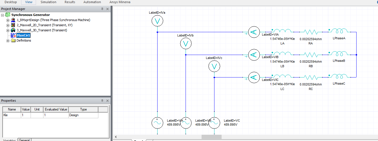
1: What is the use of MaxCir1 as shown below ?
July 15, 2021 at 6:24 amNavya Chode
Forum ModeratorHi @ranjanpal999 Below are the answers
1) What is the use of MaxCir1 as shown below ?
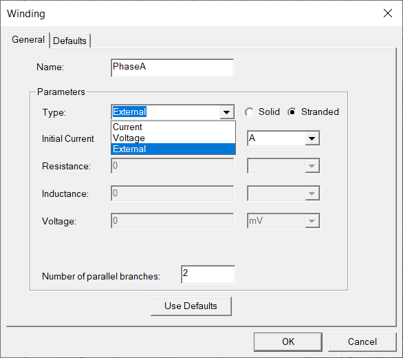
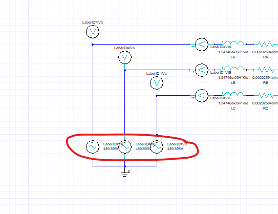
While you provide excitation you can define it directly on the window as either voltage or current and if you choose to use the external circuit you define it in the external circuit as shown in the Maxcir1.
When you do this you need to export the circuit netlist and link it back to excitation . This is implemented i the 3D model and 2D model is given direct excitation just to demonstrate both possibilities.
Right-click on excitation>external circuit.
Select create external circuit.
Create your external circuit and export the netlist.
Come back to maxwell design Right-click on excitation>external circuit.
Select import circuit netlist and you are done.
Refer Mawell help for additional information on the external circuit.
 2) Under the Excitation column, how can the stator windings be assigned a value?
This is because you can run the motor as a generator or generator as a motor. You can also add a load at the end of the three phases in the circuit instead of the voltage and see the voltage.

3) How can the no. of stator conductors be only 1 in each slot?
This model is created from RMxprt. if you look in the winding it is defined as 2 coil sides per slot . you can also change this to any number as per your design and change the conductor dimensions appropriatly.
4) If I need to simulate only 2D model, then I shall delete the Maxwell 3D model. Other than that, is there anything else that needs to be done ?
Yes. No other changes are required.
5) In actual physical sense, the rotor of a synchronous generator is made to run by an external means i.e. steam/hydraulic turbines etc. Hence, rotor speed should be an input parameter to the Maxwell model. In the inbuilt model, the synchronous generator is made to run at 750 rpm as seen from the speed graph. But, how was the speed given as an input parameter to the generator ?
This is because in the simulation world we model everything to as close to reality as possible and may not be exactly the same as the physical world sometimes. In the real world, the flow of water/steam is regulated to make the rotor of the generator run at a constant speed. Since this is an electromagnetic simulation you are replication the same by assigning the speed of rotation to the rotor(which is an input to the generator in the real world also). If you have all the minor speed variation data you can also add the using a PWL function in the motion setup.
Regards Navya
July 18, 2021 at 1:53 amranjanpal999
SubscriberHi Navya Thanks a lot for your valuable suggestions. Most of my doubts have been clarified.
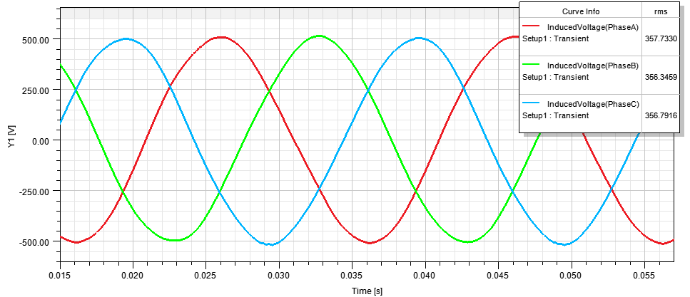
Another question to ask, from the below graph of induced voltage in stator windings, it can be observed that the V_peak=500 V and f=50 Hz.

However, could you please let me know, if I wish to have different values of V_peak and f, let's say V_peak=700 V and f=60 Hz, what changes do I need to make in RMXpert, Maxwell2D, Maxwell3D and MaxCir1 models ?
July 19, 2021 at 10:47 amNavya Chode
Forum ModeratorHi @ranjanpal999 Increase the field supply and speed according to the basic back emf formula and Synchronous speed, poles, and frequency relation - which is NS = (120*f)/P
Regards Navya
July 23, 2021 at 2:33 amranjanpal999
SubscriberHi @Navya Thanks a lot for your valuable feedback.
In our earlier conversation dated on 15th July, for my 2nd question, you mentioned that the model can work as a generator or a motor.
Please let me know whether my following understanding is correct or not:
The RMxprt model, titled as Three Phase Synchronous Machine, is unbiased i.e. the software itself does not know whether the machine is a motor or a generator.
In order to make this RMxprt model behave as a motor, the excitation (external i.e. MaxCir1) in Phase A, B and C behaves as the input voltage delivered to the stator windings delivered by AC mains or a VFD. The induced voltages as seen in the reports section, is the actual input voltage delivered to stator windings which has harmonics, due to non-linearity of inductance.
In order to make this RMxprt model behave as a generator, the excitation (voltage) in Phase A, B and C behaves as the expected output voltage from the stator windings that should be delivered to the grid. The induced voltages as seen in the reports section, is the actual output voltage generated in the stator windings that is delivered on the grid side.
Please correct me if I am wrong.
In a nutshell, how will the software know whether we want the simulation to work as a motor or a generator.
September 20, 2021 at 11:13 pmumozumder
SubscriberIn case you didn't find it yet, you can specify your machine in the Analysis. Add a new solution set up what do you want to do and the compiler will ask the necessary information from you.
February 2, 2022 at 3:47 ams3740222
SubscriberHi Ranjan Can you please help in making three phase winding for generator if you have understood?
Regards
Viewing 6 reply threads- The topic ‘Understanding Synchronous Generator’ is closed to new replies.
Innovation SpaceTrending discussionsTop Contributors-
4883
-
1587
-
1386
-
1242
-
1021
Top Rated Tags© 2026 Copyright ANSYS, Inc. All rights reserved.
Ansys does not support the usage of unauthorized Ansys software. Please visit www.ansys.com to obtain an official distribution.
-
The Ansys Learning Forum is a public forum. You are prohibited from providing (i) information that is confidential to You, your employer, or any third party, (ii) Personal Data or individually identifiable health information, (iii) any information that is U.S. Government Classified, Controlled Unclassified Information, International Traffic in Arms Regulators (ITAR) or Export Administration Regulators (EAR) controlled or otherwise have been determined by the United States Government or by a foreign government to require protection against unauthorized disclosure for reasons of national security, or (iv) topics or information restricted by the People's Republic of China data protection and privacy laws.


