TAGGED: multiphase
-
-
February 1, 2021 at 4:18 pm
Allen P Varghese
SubscriberI have set up a multiphase model in Fluent with 2 phases (gas and liquid nitrogen)
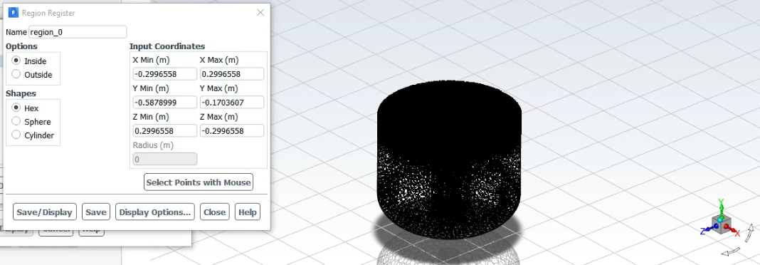
I created a region in Adapt>Cell Registers>New Region
I used Save/Display to see the defined region and everything looks good
I initialized the domain using standard method with phase2 (liquid) volume fraction as 0 over the entire domain
I then patched phase2 (liquid) volume fraction as 1 in the defined region. Please find attached screenshot of this step. Please note that I have only selected the region and I have not selected the zone. I get the message (certain number of cells have been marked).
Next to verify if the patching was done correctly, I created a contour to show the volume fraction of phase2 (liquid) but the result shows the whole domain having 0 volume fraction (implying that the region patching did not work). There are no error messages.
Attached Figures:
Region that was defined earlier in Cell Register and was patched in Fig1
February 1, 2021 at 4:35 pmRob
Forum ModeratorPut a slice down the domain, probably x=0 or z=0 and look at that. nFebruary 1, 2021 at 4:38 pmSubscriberHi Rob,nI applied a slice on XY plane and I have attached it as a figure. It also shows that the domain did not get patched.n n
February 1, 2021 at 10:14 pmSubscriberI was able to fix this by using the marked region to separate the single cell zone within Mesh>Zone>SeperatenOnce I had two cell zones, I patched each zone with respective values of phase volume fraction and I could observe the result in the initial contour.nThis however still does not explain why I couldn't achieve the same result just by patching the region. Confused (maybe a bug?).nn
n
February 1, 2021 at 10:14 pmSubscriberI was able to fix this by using the marked region to separate the single cell zone within Mesh>Zone>SeperatenOnce I had two cell zones, I patched each zone with respective values of phase volume fraction and I could observe the result in the initial contour.nThis however still does not explain why I couldn't achieve the same result just by patching the region. Confused (maybe a bug?).nn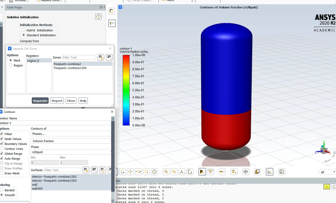 nn
February 2, 2021 at 12:39 pmForum ModeratorPatch should work, and I've been using the feature. Initialise with zero n2liquid and then patch the region. What is odd in the first plane image is the line across the image. nFebruary 2, 2021 at 3:06 pmSubscriberThat line indicates a perforated plate which is part of the model. The region I created depicts the fluid volume below the plate and I was trying to patch that region with n2liquid to 1.nI did initialize with 0 n2liquid over the whole domain and then tried to patch the marked region with n2liquid 1 but it wasn't working. I tried different models and also different meshes to troubleshoot but for some reason, regions aren't getting patched. That is when I found that cell zones are getting patched successfully, thus I split the cell zone into two and patched them as explained in the previous post.nFebruary 2, 2021 at 3:28 pmForum ModeratorOK. Looking at the mesh display what is the perforated plate defined as? nFebruary 2, 2021 at 3:34 pmSubscriberInitially I tried assigning the walls of the perforated plate as PerfWall named selection and the other boundaries as Wall named selection in DesignModeller. My intention was to apply a BOI on PerfWall once in Fluent meshing mode. I went ahead and created a region but it wasn't patchingnIn my next attempt, I named all boundaries as Wall and did not do a BOI in fluent meshing. Created the region in cell register but it wasn't getting patched either.nFebruary 2, 2021 at 3:57 pmForum ModeratorWhat concerns me is the fact that the perforated plate isn't a distinct wall. I'd expect a wall & wall:shadow pair. If the plate has a finite thickness the cell count in that area is likely to be excessive. nIf you separate the wall by angle (85 degrees ought to do it) what happens? nViewing 8 reply threads
nn
February 2, 2021 at 12:39 pmForum ModeratorPatch should work, and I've been using the feature. Initialise with zero n2liquid and then patch the region. What is odd in the first plane image is the line across the image. nFebruary 2, 2021 at 3:06 pmSubscriberThat line indicates a perforated plate which is part of the model. The region I created depicts the fluid volume below the plate and I was trying to patch that region with n2liquid to 1.nI did initialize with 0 n2liquid over the whole domain and then tried to patch the marked region with n2liquid 1 but it wasn't working. I tried different models and also different meshes to troubleshoot but for some reason, regions aren't getting patched. That is when I found that cell zones are getting patched successfully, thus I split the cell zone into two and patched them as explained in the previous post.nFebruary 2, 2021 at 3:28 pmForum ModeratorOK. Looking at the mesh display what is the perforated plate defined as? nFebruary 2, 2021 at 3:34 pmSubscriberInitially I tried assigning the walls of the perforated plate as PerfWall named selection and the other boundaries as Wall named selection in DesignModeller. My intention was to apply a BOI on PerfWall once in Fluent meshing mode. I went ahead and created a region but it wasn't patchingnIn my next attempt, I named all boundaries as Wall and did not do a BOI in fluent meshing. Created the region in cell register but it wasn't getting patched either.nFebruary 2, 2021 at 3:57 pmForum ModeratorWhat concerns me is the fact that the perforated plate isn't a distinct wall. I'd expect a wall & wall:shadow pair. If the plate has a finite thickness the cell count in that area is likely to be excessive. nIf you separate the wall by angle (85 degrees ought to do it) what happens? nViewing 8 reply threads- The topic ‘Unable to patch Cell Registered Region to define phase for multiphase simulation’ is closed to new replies.
Innovation Space Trending discussions
- JACOBI Convergence Issue in ANSYS AQWA
- Is it able to solve turbomachinery using density-based solver in Fluent?
- Two-way FSI simulation
- Ensight Force_per_unit area_EV
- RIBBON WINDOW DISAPPEARED
- Fluent Meshing Error when .dsco not .stp
- Ansys Fluent for modelling Ocean Wave reactions to Wave Barriers
- Battery Pack cooling
- ISAT ABORT error
- UNASSIGNED INTERFACE ZONE DETECTED FOR INTERFACE…
Top Contributors
-
peteroznewman
 4592
4592 -
scabo
 1494
1494 -
Dennis Chen
 1386
1386 -
javat33489
 1209
1209 -
Shyam Prasad V Atri
1021
Top Rated Tags
© 2025 Copyright ANSYS, Inc. All rights reserved.
Ansys does not support the usage of unauthorized Ansys software. Please visit www.ansys.com to obtain an official distribution.
-