

-
-
January 16, 2021 at 3:34 pm
Nishanth
SubscriberHello,
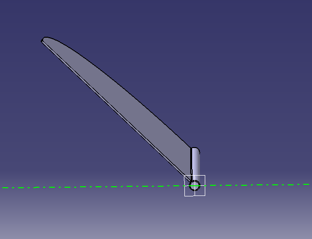
I've been trying to perform a CFD analysis of a flapping wing. Please view the attached images.
I have taken a flat rectangular wing inclined at an angle of 45d to the wingspan-axis and 15d to the fuselage-axis.
January 16, 2021 at 8:38 pmYasserSelima
Subscriberwhen you are creating the lift report, what is the direction of lift? you will see x, y and z values nJanuary 17, 2021 at 7:05 amSubscriberHey, I'm measuring lift at (x, y,z = 0,0,1). Where z is the vertical axis. nThe sign convention is also proper, The Z-axis line on Ansys faces upwards. nJanuary 17, 2021 at 8:36 amSubscriberdid you complete 360 degrees rotation?nJanuary 17, 2021 at 11:25 amSubscriberdid you complete 360 degrees rotation?/forum/discussion/comment/103352#Comment_103352
No, Just 60 degrees downwards and 60 degrees upwards which will send it back to the original position. Mimicking flapping motion.nJanuary 17, 2021 at 12:28 pmSubscriberUPDATE: The lift is positive when I do a static analysis at -15d and 60d dihedral. But as soon as a start the mesh motion the lift goes negative! nPlease help. nJanuary 17, 2021 at 3:52 pmSubscriberI think it will be -ve for 180 degrees and positive in the other 180 degree. This what I expect from your geometry. Try moving it 360 degreesnJanuary 18, 2021 at 2:46 pmSubscriberI think it will be -ve for 180 degrees and positive in the other 180 degree. This what I expect from your geometry. Try moving it 360 degrees/forum/discussion/comment/103368#Comment_103368
Not working. nI think the problem is with the boolean. Because when I check streamlines, I can hardly see them go in the rotating wall. The values are negative but are nearly zero.nCan you please check if the way I have performed my boolean is correct? Because when I try to hide the face I need to hide the face of the rotating wall twice. nJanuary 18, 2021 at 3:21 pmSubscriberIf you have a wall and wall shadow, this means you identified the flapping wing as solid. This is not required if you do not have FSI. You can just make it as a gab. nI would suggest decreasing the duct dimensions trying to force the flow to enter your moving frame. Another solution is to use UDF to rotate the wing instead of the MRF. But this will require some work from you.nJanuary 18, 2021 at 5:02 pmAmine Ben Hadj Ali
Ansys EmployeeWhat kind of boundary separates the rotating zone from non rotatingnViewing 9 reply threads- The topic ‘unable to get positive lift values for a flapping wing analysis’ is closed to new replies.
Innovation Space Trending discussions
 Top Contributors
-
peteroznewman
 4909
4909 -
scabo
 1598
1598 -
Dennis Chen
 1386
1386 -
javat33489
 1242
1242 -
Shyam Prasad V Atri
1021
Top Rated Tags
© 2026 Copyright ANSYS, Inc. All rights reserved.
Ansys does not support the usage of unauthorized Ansys software. Please visit www.ansys.com to obtain an official distribution.
-


The Ansys Learning Forum is a public forum. You are prohibited from providing (i) information that is confidential to You, your employer, or any third party, (ii) Personal Data or individually identifiable health information, (iii) any information that is U.S. Government Classified, Controlled Unclassified Information, International Traffic in Arms Regulators (ITAR) or Export Administration Regulators (EAR) controlled or otherwise have been determined by the United States Government or by a foreign government to require protection against unauthorized disclosure for reasons of national security, or (iv) topics or information restricted by the People's Republic of China data protection and privacy laws.


