General Mechanical

General Mechanical

Topics related to Mechanical Enterprise, Motion, Additive Print and more.

Ultrasonic horn gain analysis

    • Damien Piel
      Subscriber

      Hello all,

      I'm actually doing an analysis on the ultrasonic welding and I'm looking to find the gain of the welding horn. About the welding, I already know the amplitude of the converter and the gain of the booster.

      To find the gain of the horn, I'm looking to use the software ANSYS with Modal analysis, for know, I just simulate the natural frequency, and I found the reasonance frequency around 30kHz where the horn have Y displacement.

      Actually, I'm looking to find the gain of the horn, so the idea is to put an excitation at the top of the horn and looking the displacement at the bottom to find the gain.

      In transient analysis, I put this type of displacement with the amplitude and the frequency : A*sin(2*pi*f*time) with f=29589. And I add the acceleration of the gravity.

      Actually my result don't looks good because the frequency from input and output is different:

      Actually, I'm not sure about my way to find the Gain of the horn, if someone have some ideas to increase my methode.

      Thank you for your support,

      Damien

    • Erik Kostson
      Ansys Employee


      Hi

      I can not help with your question (gain).

      Something that might help. We can analyze the whole device using coupled field harmonic or modal.

      An example is in the help manual:

      Chapter 39: Wire Bonding Ultrasonic Transducer (ansys.com)


      See here how to access the above link:

      /forum/forums/topic/how-to-access-the-ansys-online-help/

      All the best

      Erik


    • peteroznewman
      Subscriber

      Hello Damian,

      I read this ultrasonic horn design guide and suggest you stay with Modal analysis.  Don't use any boundary conditions. This is called a Free-Free Modal Analysis.  Request a lot of modes, say 20. Plot all the modes but ignore the first 6 as they have zero frequency and are known as the rigid body modes.  Look at each animation from mode 7 and above to find the modes that have an axial deformation.  For those modes, plot the Directional Deformation instead of the Total Deformation and select the coordinate direction that is parallel with the axis of the horn.  Now you can see the displacement of the base and the displacement of the tip.  The ratio of those displacements is the gain of the horn, which the article calls the Step-up.

      You could use modal cyclic symmetry, which enables you to review the mode shapes of a cyclically symmetric structure by modeling just a sector of it.

      You could create axisymmetric geometry by placing the axis of rotation along the Y axis and slicing the 3D geometry in the XY plane and the YZ plane then keep the face that is on the +X side of the XY plane and discard all other faces. In that way, there will only be one zero frequency mode and no bending or twisting modes to look at. This would be more efficient, but will take some extra time to prepare the geometry.

    • Damien Piel
      Subscriber

      Hello all,

      thank you for your support, it's help me a lot.


      To find the gain, I have to define a Modal and a Hamonic Response setup :

      To define the excitation, you have in the harmonic response, to activate the Base excitation and add an Magnitude.

      After that, you will have an output with an infinte amplitude, so you have to add some damping ratio.


      Conclusion :  the damping ratio is very important, so you need the exactly ratio to find the good gain, I'm not sure that the simulation is the best way to find the real gain.


      Thank you,

      Damien

    • Damien Piel
      Subscriber

      With the damping ratio, is looking more like this chart, so it's possible to have the maximum :

    • peteroznewman
      Subscriber

      With the Displacement BC in Modal, what shape was the first mode? Was it axial or was it bending or torsion? It's possible that the first mode was a bending mode, while the axial mode was at a higher frequency.  You want to look at the Harmonic Response near the frequency of the axial mode.

      I see you created two Directional Deformation results in the Modal analysis. Did you try doing the Free-Free Modal (delete the Displacement BC)?  Did you find which mode had axial (not bending or torsion) vibration?  For the axial mode, what was the ratio of the deformations?  Just curious to compare that ratio with the peak amplitude of the Harmonic Response.

    • Damien Piel
      Subscriber

      Actualy, I'm looking for the shapes between 25 kHz and 35 kHz, because it's a 30 kHz ultrasonic Hz, 


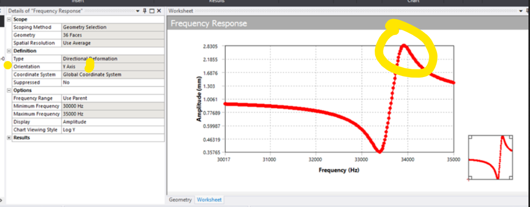
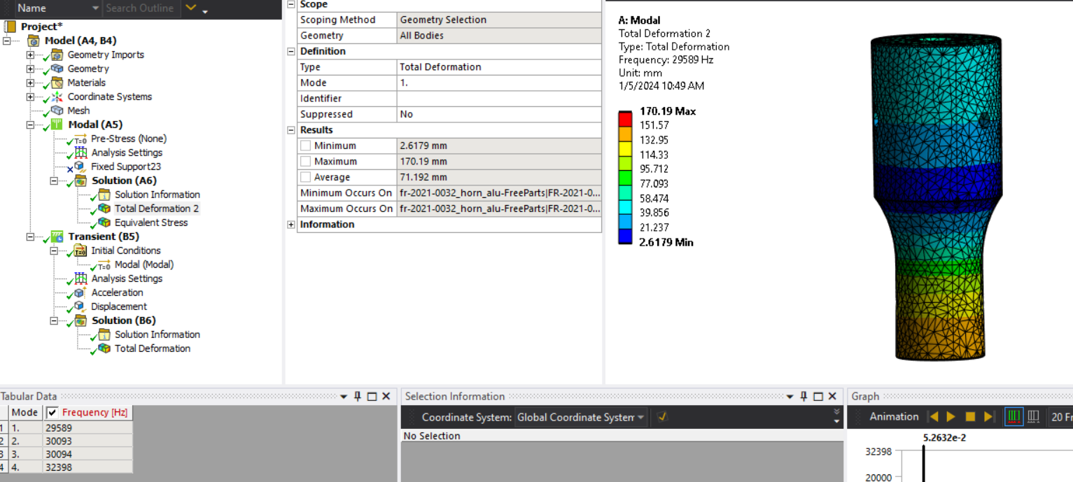
      Natural frequency for displacement around Y direction, so axial deformation:
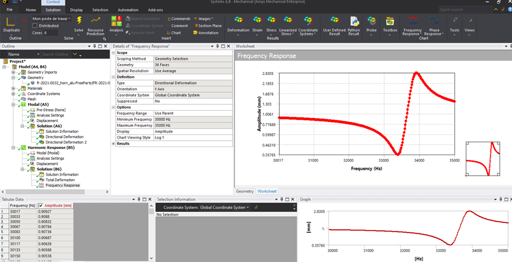
      • With BC : 33854 Hz
      • Without BC : 29589 Hz

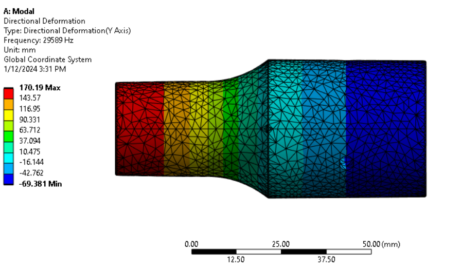
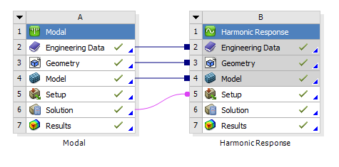
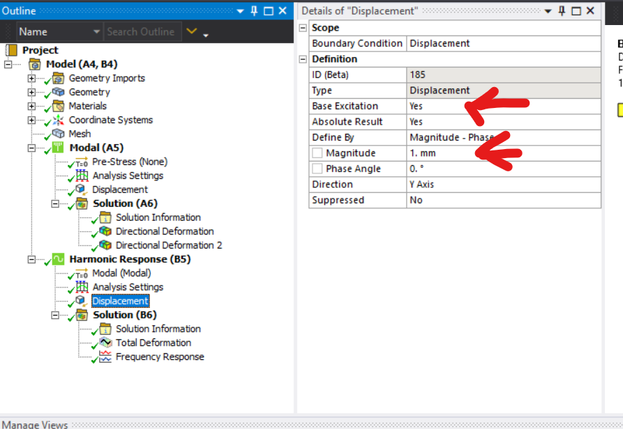
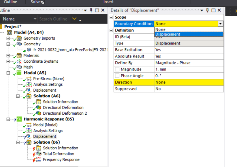
      Normaly it's a ultrasonic horn for 30 kHz, so I prefer the results without BC, and theoricitaly, I think that we do like that. The things is that we want to use the coupled setup "Modal - Harmonic-response" the create an exitation with a magnitude, we need to use a BC with Y direction from "Modal anlysis". I'm not sure that we can create a excitation on Free-Free modal analysis.


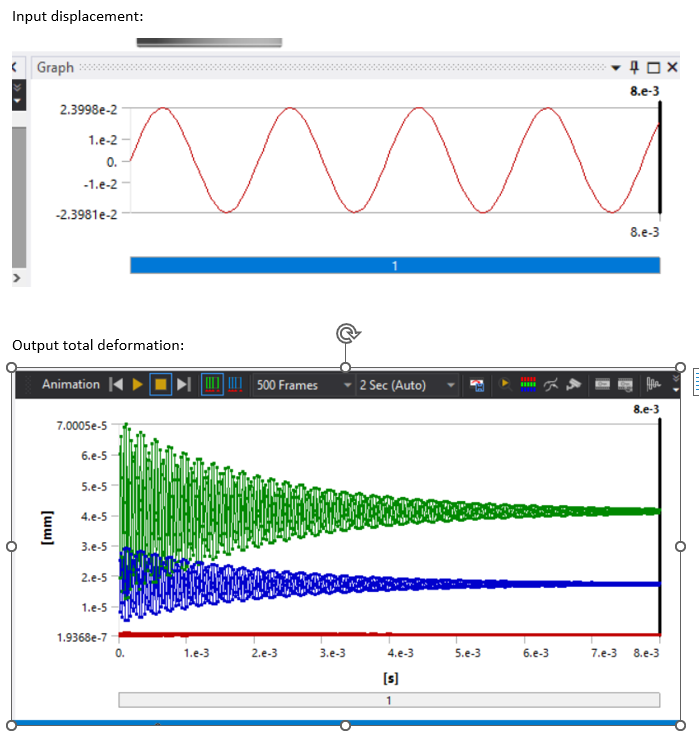
      "For the axial mode, what was the ratio of the deformations? "

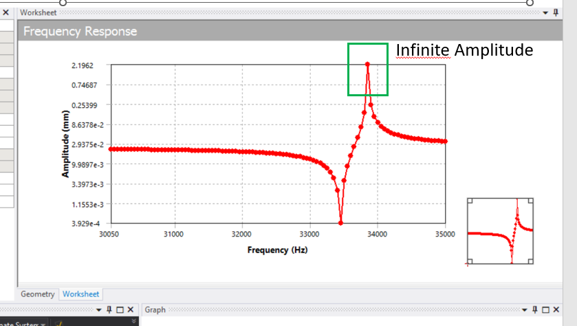
      Indeed, for the axial mode along Y, the amplitude is define by the damping ratio if we don't want an infinite amplitude


    • peteroznewman
      Subscriber

      Using just the Free-Free Modal, I can estimate the gain by using the ratio of 170/69.4 = 2.45. I think this is what the software in the link I provided is doing to report the "Step-Up" value. Note that the gain estimate from the Free-Free Modal is less than the gain estimate of 2.83 from the Harmonic Response using a Base Excitation with some damping. Maybe you can adjust the damping in the Harmonic Response until the gain matches the estimate from the Free-Free Modal analysis.

Viewing 7 reply threads
  • The topic ‘Ultrasonic horn gain analysis’ is closed to new replies.