-
-
April 9, 2026 at 12:12 pm
SR786
SubscriberHi,
I am currently interested in modelling semi-batch precipitation in a stirred tank using the method of moments approach. I am treating the flow as pseudo-homogeneous (Stk << 1), so I will not be using an inhomogeneous two-fluid solver. Also, I am tracking vortex shape. The current models I have:
- VOF (track gas-liquid interface)
- RANS (SST k-w CC)
- Species Transport (track depletion of reacting species)
- User Defined Scalar (track crystal properties via population balance where scalars represent moments)
A UDF is used to calculate kinetics (nucleation and growth) and link species and uds equations via source terms.Â
I have managed to run a simulation with a batch operation (no feed) with all flow equations switched off and the simulation works fine with physically realistic results. However, when I attempt to model semi-batch operation with flow equations switched on I am noticing some major issues, in particular the moments calculated (i.e., zeroth moment) becomes unrealistically large which has a cascade effect on crystal properties as mass and size become unphysical. As far as I am aware, the simulation set-up from the GUI has been optimised in terms of settings and numerical schemes.Â
I am unsure of where to proceed from here, one thing that I can think of is that currently my source terms are non-linearised. I am aware this means the source terms are treated explicitly and can have a big impact on numerical stability. Given the complexity of what I am trying to simulate (especially for semi-batch process), is it recommended to linearise source terms and how would I do that. Currently the source term for zeroth moment is:
S(m0) = alpha*rho*B
[dS(m0)] = 0
Where alpha = volume fraction of liquid; rho = liquid density; B = Nucleation rate, B = kb*(sigma)^b. where kb and b are constants and sigma is the supersaturation driving force.
I do not know how to linearise this term
-
April 9, 2026 at 1:17 pm
Rob
Forum ModeratorLinearisation or some other limiter may be a good idea. What is stopping the UDF from trying to turn the whole tank into the smallest crystal/precipitate instantly on the first time step?Â
-
April 9, 2026 at 1:40 pm
SR786
SubscriberHi, thank you for the reply. I have plotted some contours of supersaturation (top) and zeroth moment (bottom) which represents the number density of particles. Essentially with a semi-batch process with slow feed and fast reaction we should see a segregated feed with localised region of high supersaturation near feed where nucleation is dominant and low supersaturation which slowly builds up in the bulk which is growth dominant. Nucleation and growth aren't activated until supersaturation driving force exists is (S > 1)
What I am finding is that the m0 value is giving an unphysical value and you can see from the contours that after 2.5 s it just increases out of control and I'm really stuck as to how to control this. Another noticeable is there are negative m0 values, despite supersaturation and nucleation having a minimum value of 0. You mentioned applying a limiter, how would I do this?
Â
Â
-
April 9, 2026 at 2:36 pm
SR786
SubscriberI remember once you mentioned: "You may also need a limiter to stop your UDF source term from exceeding the solid packing limit: that doesn't lead to a stable solution." in a previous thread (https://innovationspace.ansys.com/forum/forums/topic/udf-for-crystallisationprecipitation/) when I was trying to set up my UDF structure. I didn't do this (and for my uncoupled batch pbe simulation there weren't any notable issues as compared to my current coupled semi-batch pbe simulation). Could this be the source of the instability and why m0 is increasing uncontrollably?
-
April 9, 2026 at 3:36 pm
Rob
Forum ModeratorThe packing limit refers to Eulerian-Granular models. There the granular phase has a packing limit as you can't have 100% solid, but a UDF source doesn't know what the volume fraction is unless you tell it. Even then, with a runaway case, you can create more solid than can fit which causes problems with stability.Â
In your code what interactions could lead to a runaway? Ie what feedback possibilities are there?Â
-
April 9, 2026 at 3:42 pm
Rob
Forum ModeratorAnd for a limiter you "just" apply a max source term. So in general terms:
rate = stuff * other stuff
source = rate
IF source > a number, source = a smaller number
return source
-
April 10, 2026 at 8:38 am
SR786
Subscriber
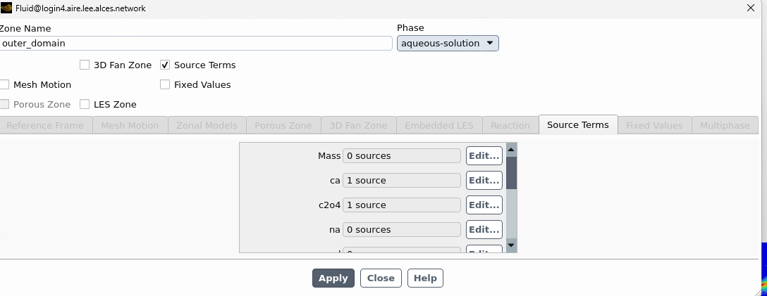
Okay, I'm not sure a packing limit applies to my code as I am not using eulerian-granular model, just homogeneous VOF for gas-liquid flow field and treating solid as scalar. I'm confused as my code worked with a batch simulation, albeit the simulation was decoupled, i.e., I froze the flow field and solved only species and scalar transport. I cannot freeze flow field for my semi-batch as there is a feeding period where liquid level will rise and that can only be captured with full coupling.Â
The stiffness is the code is caused by the tight degree of coupling between the species transport and scalar transport, particulalry the source terms.
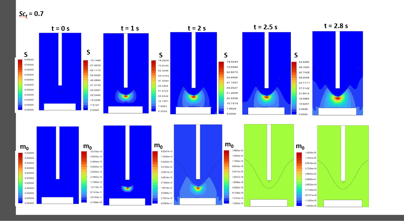
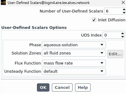
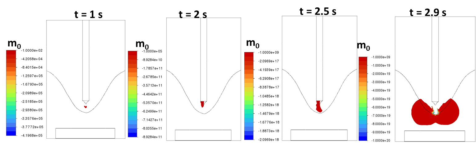
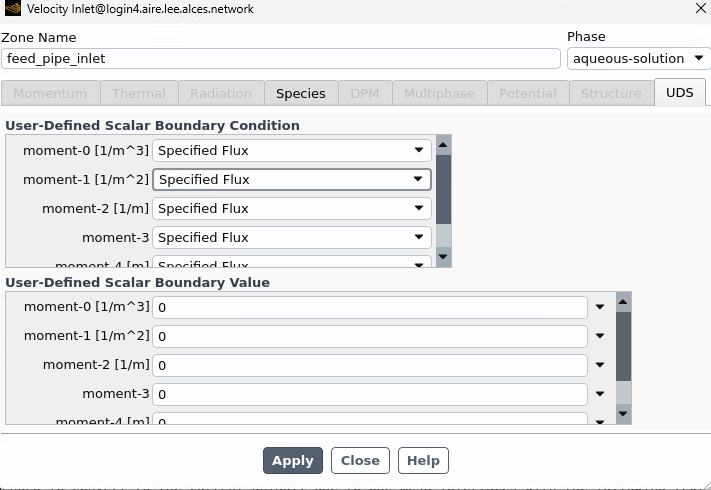
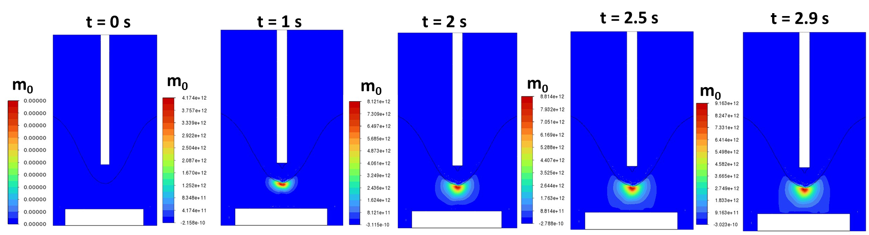
For scalar (represented as moments), the source term is:
S(m_n) = alpha*rho*[0^n*B + n*m_(n-1)*G]
The species are linked to the second moment by following source term:
S(Y_i) = -(3*m2*G)*kv*rho_c*(mw_i/mw_c)
In these equations, B and G are the nucleation and growth rate which are function of k_i(S-1)^i. Nucleation has large rate constant, kb = 5*10^9 [1/m^3/s] due to fast reaction whereas growth as small rate constant, kg = 6.67*10^-10 [m/s].
I am already following best guidelines online for these type of simulation in terms of numerical schemes, though every simulation that was done before did not incorporate VOF and instead treated liquid surface as flat.Â
-
April 10, 2026 at 8:51 am
Rob
Forum ModeratorIs the species source just on species or on mass too? How are you handling energy? If there's virtually no species in a cell what stops your source trying to create too much scalar value?Â
For a fixed flow any runaway won't then trigger gradient problems in the other equations (energy being a good one to fail as you add/remove silly amounts of heat). Is the scalar limited to the liquid phase only?Â
-
April 10, 2026 at 9:01 am
SR786
SubscriberHi,
Okay I only apply source terms to liquid phase only. Species source is only activated for reacting ions. Also scalar source terms are activated too. Energy equation is deactivated as I am assuming isothermal conditions and I defined the scalar to the liquid phase only.
Note: In the feed pipe only liquid should be coming out, all scalar fluxes at inlet B.C are set to zero. I have noticed that inlet diffusion is activated by default. Could this be contributing to simulation instability for semi-batch which has feed b.c as compared to batch which is a closed system.
-
April 10, 2026 at 10:58 am
Rob
Forum ModeratorInlet diffusion only matters if the flow is low enough that you can diffuse more material in than can flow. Turning it off may help. I assume all 6 scalars are set the same?Â
In the source terms you're adding/removing two species only? What is the density of whatever is being added/removed? Note, overall mass is constant from source terms but you're altering species fractions.Â
Â
-
April 10, 2026 at 11:05 am
SR786
SubscriberYes all the scalar terms are the same. Also my feed rate is very small, 1.11*10^-6 m^3/s. I was thinking that this may be the reason why I am seeing negative moments in my simulation, which should not be possible, due to this inlet diffusion. The dispersion of negative moments is then causing all the moments to blow up.
For the source terms, yes only two species react the other two remain in solution as it is based on precipitation of calcium oxalate (s) by mixing calcium chloride (aq) and sodium oxalate (aq). The source term equation is based on specific growth rate of crystal as per literature with density term based on crystal density (2200 kg/m^3).
Â
-
April 10, 2026 at 12:45 pm
Rob
Forum ModeratorYes, that could be a cause. As well as scalar diffusion check the species model.Â
If you are reacting two species to create the precipitate, and I can see two species with sink/source, where is the third?Â
-
April 10, 2026 at 12:53 pm
SR786
SubscriberNo problem I will check for both models.
For this population balance you don't need to model the third precipitate species explicitly as you already get the crystal properties from the moments, i.e., number density (zeroth), length (first), surface area (second), volume/mass (third), etc which are interlinked with the species balance.
-
April 10, 2026 at 1:04 pm
Rob
Forum ModeratorYes... Where is the mass going from those species though? If there's no mass sink the last one in the list will make up the mass/volume.Â
-
April 10, 2026 at 1:09 pm
SR786
SubscriberSo the mass of the species contributes the third moment term which is proportional to mass of crystal. I track mass of crystal by using formulae: mass = kv*rho_c*m3 where kv is shape factor and rho_c is crystal density. This is how I track mass balance and check mass produced does not exceed theoretical mass. I have assessed crystal mass in batch simulation which gave reasonable results.
-
April 10, 2026 at 1:36 pm
Rob
Forum ModeratorOK. In Fluent if you add/remove species without a corresponding mass source you'll (probably) lose/gain the last species in the list to meet mass conservation.Â
-
April 10, 2026 at 1:39 pm
SR786
SubscriberAh okay, the last species in my list which is not explicitly solved and instead calculated by Y_j = 1 - SUM(Y_i) is the water which is in excess as compared to the concentration of ions which are dilute
-
April 10, 2026 at 1:50 pm
Rob
Forum ModeratorYes. But depending on what you're losing, and how quickly, I can't say what that will do to mass/volume in the cell.Â
-
April 13, 2026 at 11:58 am
SR786
SubscriberOkay no worries, thank you for the advice. Interestingly I have also tried plotting my scalar quantity m0. There should be no feed for scalar coming from pipe (set to value of 0) as only liquid is discharged, but what I am observing over period of feed addition is plume develops for the scalar quantity and has a negative vale. This plume grows in size and magnitude reaching very large negative values which eventually disperse in the liquid. At the point it grows large in size and disperses in the liquid is when I lose control of my solution and get garbage values for crystal mass. Is this a strong indicator that inlet diffusion of UDS is causing this effect as I don't know how a negative feed plume is forming.
-
April 13, 2026 at 12:13 pm
Rob
Forum ModeratorThat could also scalar convergence not being good. UDS don't have all of the extra stability functions that species etc have so they can be more sensitive to mesh, time step etc.Â
-
April 13, 2026 at 12:20 pm
SR786
SubscriberNo worries, I already have a refined mesh (see mesh cross section below) near the feed pipe using polyhedral mesh whoch is known to be better than tetrahedral for gradient calculations and I am tightly controlling time step with time step size of 5e-5 s (CFL = 0.55) and low URF for UDS with 0.2. My residuals for UDS actually do converge to < 10^-5 but the solution I get is garbage. That's sort of why I'm now leaning towards this inlet diffusion problem, especially after analysing contour.
-
April 13, 2026 at 12:32 pm
Rob
Forum ModeratorHow is m0 negative in the first place?
-
April 13, 2026 at 12:42 pm
SR786
SubscriberI am not sure why m0 is giving a negative value as according to my solver set-up:
At t = 0; m0 = 0.
For t > 0: the solution becomes supersaturated (S > 1) from mixing with feed causing m0 to increase with nucleation rate as S_m0 = B and B = (S-1)^b. When S < 1, B is deactivated so B = 0 and therefore S_m0 = 0 so there cannot be a negative source term for m0.Â
The first thing I checked was if Fluent was giving negative values for B as this would result in S_m0 < 0 and negative m0. I checked and the minimum value of B was 0.Â
All the scalar values at inlet B.C are set as 0 (under specified value condition). So the only other thing I can think of is that inlet diffusion was activated for my semi-batch simulation. For my batch simulation I did not observe negative moments likely because the system was closed and so I didn't have an inlet B.C.
Â
-
April 13, 2026 at 1:31 pm
Rob
Forum ModeratorWhich comes back to convergence. Are you using fixed value on the inlet, or fixed flux?
-
April 13, 2026 at 1:35 pm
-
April 13, 2026 at 1:55 pm
SR786
SubscriberShould I use specified flux or specified value for UDS at inlet?
-
April 13, 2026 at 3:23 pm
Rob
Forum ModeratorDepends what it's for! Might make sense to fix a zero value somewhere to anchor the UDS.Â
-
April 13, 2026 at 3:26 pm
SR786
SubscriberYes, I have also checked some literature papers who have done a similar method to me (using UDS to define scalar moment transport in CFD-PBE) and they mention setting Dirilecht B.C for inlet and leaving Neumann B.C for walls. I will run a new simulation and check if it is able to resolve this issue.
-
April 20, 2026 at 9:35 am
SR786
SubscriberHi,
I wanted to revist this point you made: 'OK. In Fluent if you add/remove species without a corresponding mass source you'll (probably) lose/gain the last species in the list to meet mass conservation.'
So my source term is:
S_i = +/- (3*m2*G*kv) *Mw_i/Mw_crystal
My overall reaction is forming calcium oxalate monohydrate:
Ca^(2+) + C2O4^(2-) + H2O ---> CaC2O4.H2O
I only added two species terms, calcium and oxalate ion and not the precipitate nor water (last species). I assumed I didn't need them, but for my CFD-PBE solver it won't know where mass is going and it may not be conservative.
Do I need to add another species for the CaC2O4.H2O and as water is the final species, I can only set its source term by setting total mass source to zero as:
S_total = S_product - S_reactant = 0
-
April 20, 2026 at 11:04 am
Rob
Forum ModeratorOK, so you're removing two "named" species plus water but not specifying where it's going? The complication is it's a mass sink/source as opposed to mole based. If you remove & add the three "named" species, the water should be added/removed based on the terms in the "named" sources: ie it'll balance.Â
The problem is you're then using UDS to track the moments, and UDS are not necessarily linked and don't have a volume fraction limit etc.Â
-
April 20, 2026 at 11:08 am
SR786
SubscriberÂ
Yes, the UDS isn’t explicitly linked to species balance, so I need a pseudo-precipitate species in my species mixture model to make up lost mass. I believe this is what some key papers have done as well for CFD-PBE modelling where they treat flow as pseudo-homogeneous so they solve for single phase flow and implement PBE via UDS.
Edit:
Otherwise it will make up lost mass elsewhere (i.e., from water)
Â
-
April 20, 2026 at 11:11 am
SR786
SubscriberAlso my source terms are mass based rather than mole based in alignment with units of species transport. The source terms are scaled by this molecular weight fraction (Mw_i/Mw_crystal).
So for 1:1 stoichiometry:
Mw_Ca/Mw_crystal + Mw_C2O4/Mw_crystal + Mw_H2O/Mw_crystal = Mw_crystal/Mw_crystal = 1
-
April 27, 2026 at 1:08 pm
SR786
SubscriberI believe I have now resolved the issue of the unphysical crystal mass. The primary culprit appeared to be a wrong B.C set for inlet UDS, where I now use Dirilecht B.C with value of 0 for UDS. By correcting for this, now my UDS remain physical and my values do not explode. I will still also set S_total = 0, to keep mass balance conservative and avoid mass increase of last species (in my case the solvent water) to account for loss of mass from reactants
-
- You must be logged in to reply to this topic.
-
6269
-
1906
-
1457
-
1308
-
1022
© 2026 Copyright ANSYS, Inc. All rights reserved.


