-
-
September 18, 2022 at 5:35 pm
javat33489
SubscriberHello dear forum users.
I wanted to consult about the campaign to solve one problem.
There is a pipeline running from the pump along the base floor, it is attached to the base with clamp supports on the racks (rigidly). The basis - a metalwork from a channel.
The pump nozzle transmits forces in the form of moments to the pipeline, in addition, there is pressure in it.
The purpose is to check, the moments from the pump + the pressure in the pipeline = will there be vibration on the base?
One of the solutions is model analysis, natural frequencies, calculation for vibration as a result of resonance.
We consider the design moments from the pump + pressure in the pipeline (the supports are fixed rigidly at the base of the supports) in the loaded state to natural frequencies.
We consider the base separately for natural frequencies.
If there is a coincidence of frequencies, vibration occurs at that moment. Well, in theory, it will probably be necessary to look at the latest indicators in both calculations.
What do you think about this? Thank you.
-
September 18, 2022 at 7:06 pm
peteroznewman
SubscriberImages of the geometry would be helpful.
-
September 19, 2022 at 4:48 pm
javat33489
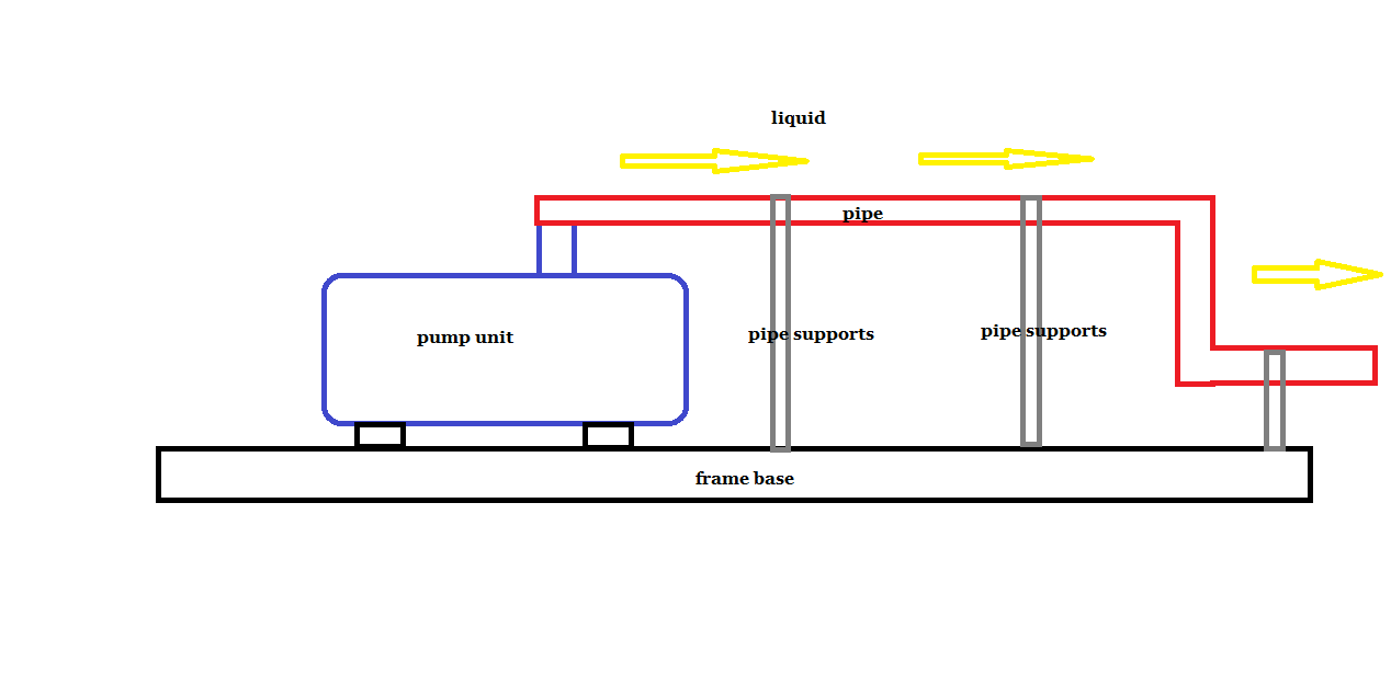
SubscriberFrom the pumping unit (blue) the load is transferred in the form of moments to the pipe (red)
The pipe is fixed with supports (grey) to the base (black) There is fluid pressure in the pipe
I need to calculate what vibration the pipe transmits from the pumping unit to the base. And determine if the vibration is acceptable.
-
-
September 19, 2022 at 5:54 pm
peteroznewman
SubscriberHow does the frame base connect to the ground? Are there four mount points that are fixed to ground? I suggest a beam model of the frame base, pipe supports and pipe be made. The pump unit can be represented as a rigid body whose mass matches that of the pump. A Modal analysis will show the free vibrations of that structure. You should add a Distributed Mass on the pipe elements to represent the weight of the liquid in the pipe.
-
September 19, 2022 at 7:04 pm
javat33489
Subscriber>>How does the frame base connect to the ground? Are there four mount points that are fixed to ground?
Yes, the base is firmly fixed to the ground
>>A Modal analysis will show the free vibrations of that structure. You should add a Distributed Mass on the pipe elements to represent the weight of the liquid in the pipe.
Just to check free vibrations? And all?
If there are free vibrations, then there is vibration; if there are no free vibrations, then there is no vibration. Right?
-
-
September 19, 2022 at 7:30 pm
javat33489
SubscriberBut then with what to compare the obtained frequencies in the model analysis? To understand if this is acceptable?
-
September 19, 2022 at 11:51 pm
peteroznewman
SubscriberIf you perform a Modal analysis, it will reveal what frequencies the structure can vibrate at, and what shape those vibrations will take. To do this, the correct mass and stiffness of the structure must be used. That is why you will get a different natural frequency when the pipe is filled with air than when it is filled with liquid.
After you have done a Modal analysis, you can add on a Harmonic Response analysis. That will tell you the amplitude of the vibration everywhere on the structure when a sinusoidal force or moment or pressure load is applied somewhere on the body. The Harmonic Response analysis will show you how the structure vibrates as the sinusoidal load sweeps from a low frequency to a high frequency. An example of that is a pump with an impeller or rotor that has some small unbalance. As the pump RPM changes, the structure will vibrate with a small amplitude until the RPM reaches one of the natural frequencies found in the Modal analysis, then the amplitude will grow much larger.
-
September 20, 2022 at 4:05 pm
javat33489
SubscriberBut what is the criterion that the design is suitable or unsuitable according to the results of the calculation?
-
-
September 20, 2022 at 5:49 pm
peteroznewman
SubscriberThe harmonic response will show you the peak stress in the model over a range of frequencies. There could be many requirements on the design. One example of a requirement is: The peak stress in the structure shall stay below the fatigue limit of the material at operating frequencies (RPM). Another example of a requirement is: The peak stress in the structure shall stay below the yield strength for any frequency below operating frequencies. In other words, during startup and shutdown the pump may pass through a resonant frequency which will create larger values of stress. Lower values of stress are found at the operating frequency but because it stays at that frequency for a long time, fatigue failure is a concern.
-
September 20, 2022 at 7:13 pm
javat33489
SubscriberSo far, everything is clear. Thanks a lot! I will test, if there are questions, I will write here! Thanks again!
-
-
- The topic ‘Transmission of vibration between structures’ is closed to new replies.


-
3477
-
1057
-
1051
-
940
-
912

© 2025 Copyright ANSYS, Inc. All rights reserved.


