-
-
April 21, 2024 at 9:16 am
Foo Sin Khai
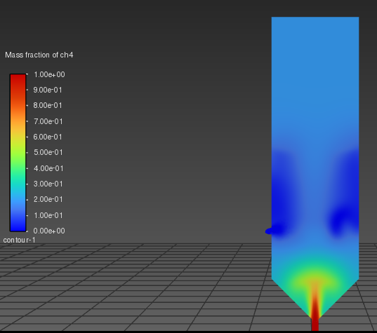
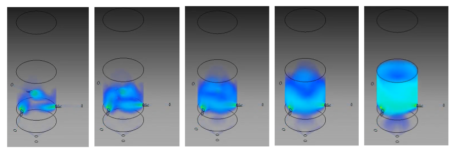
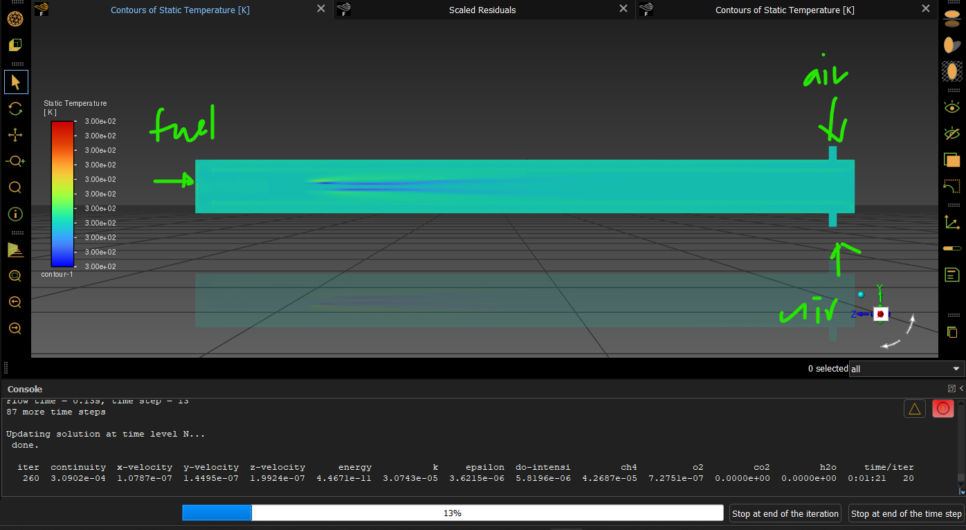
SubscriberHey there! I'm currently tackling a transient simulation of combustion in porous media. However, I've hit a snag—I'm having trouble observing combustion within the porous zone, even though it's working fine in other regions. I'm not sure if ANSYS is capable of handling transient combustion simulations in porous zones. Does anyone have any insights or expertise they could share? I've provided a detailed explanation of my scenario and problem in the picture I've posted. Any help would be greatly appreciated!
.png)
-
April 22, 2024 at 10:25 am
Rob
Forum ModeratorPlease post some more images and include scales. There's something odd in the contour(?) image so very difficult to see what's going on. Velocity, temperature & species for a start, centre-plane.
-
April 23, 2024 at 11:25 am
Foo Sin Khai
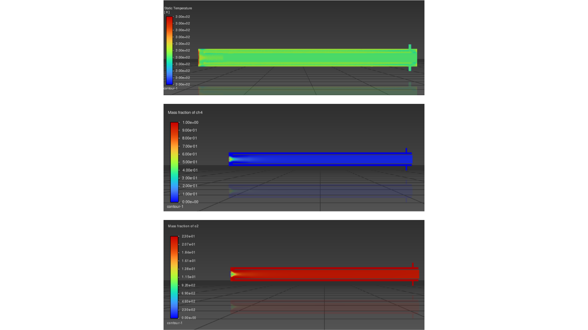
SubscriberThank you for your response. Please find the attached picture below, along with the link to the transient simulation video.
Link: https://youtu.be/8R6jViyPdu4 -
April 23, 2024 at 12:29 pm
Rob
Forum ModeratorYou may need to adjust the scale to better understand what's going on. How are the other species looking?
-
April 23, 2024 at 12:55 pm
Foo Sin Khai
SubscriberUpon viewing the video, you'll notice that the combustion remains confined to the non-porous media zone, failing to extend into the porous zone. This raises the question of whether combustion can indeed occur within the porous zone for transient?
-
April 23, 2024 at 1:05 pm
-
April 23, 2024 at 1:11 pm
-
April 23, 2024 at 1:35 pm
Rob
Forum ModeratorI've not watched the video - if you recheck the rules you'll see I'm not permitted to open links or download files. Please check what the boundary is at the ends of the second porous media - a rescaled velocity plot may also illustrate the issue.
-
April 23, 2024 at 2:46 pm
Foo Sin Khai
SubscriberAlright, I apologize for the oversight. However, I'd like to mention that the boundary condition between the second porous media and the combustion zone is of the interior type, as indicated in the picture below. Additionally, I have rescaled the velocity contour to visualize smaller velocity differences, but I am still unable to resolve the issue at hand. Would you be able to provide further assistance?
-
April 23, 2024 at 2:58 pm
Rob
Forum ModeratorOK, thanks. Interior is correct, it looked like there was near enough zero flow in the second region hence wanting the adjusted scale. The lack of flame may be linked to a lack of fuel in the second porous region, can you go through the settings to see what's going on?
-
April 23, 2024 at 4:44 pm
Foo Sin Khai
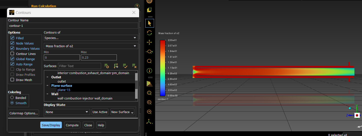
SubscriberRegarding the issue of the lack of fuel in the second porous region that you mentioned, the mass fraction contour of CH4 as shown in picture below indicates that the fuel concentration in the porous zone is similar to that in the combustion zone. Based on this observation, one would expect that since the contour of the mass fraction of fuel and CH4 is the same, there should be an adequate amount of fuel present in the porous zone. However, I'm unsure if my understanding of this is correct.
-
April 23, 2024 at 5:00 pm
-
April 23, 2024 at 11:52 pm
-
April 24, 2024 at 10:17 am
Rob
Forum ModeratorWhat is the outlet temperature set as?
-
April 24, 2024 at 10:46 am
Ren
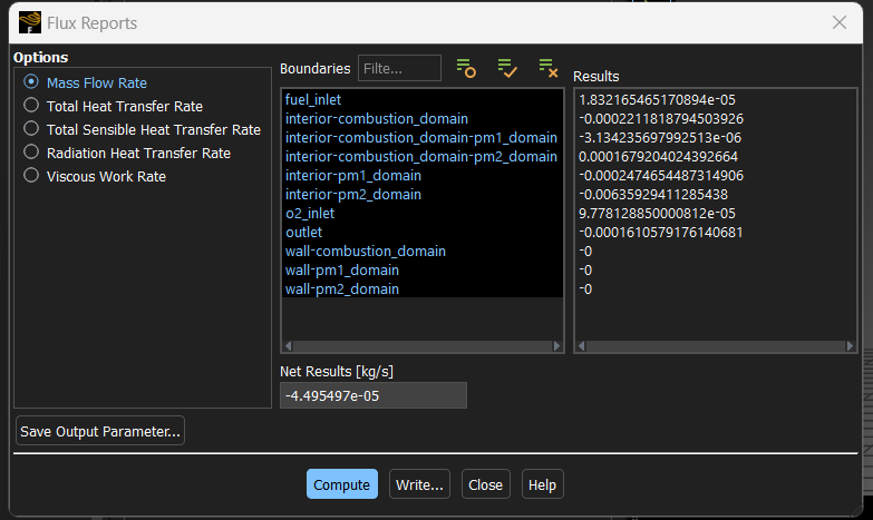
Ansys EmployeeCould you report the mass flow rates of fuel (CH4) and air?
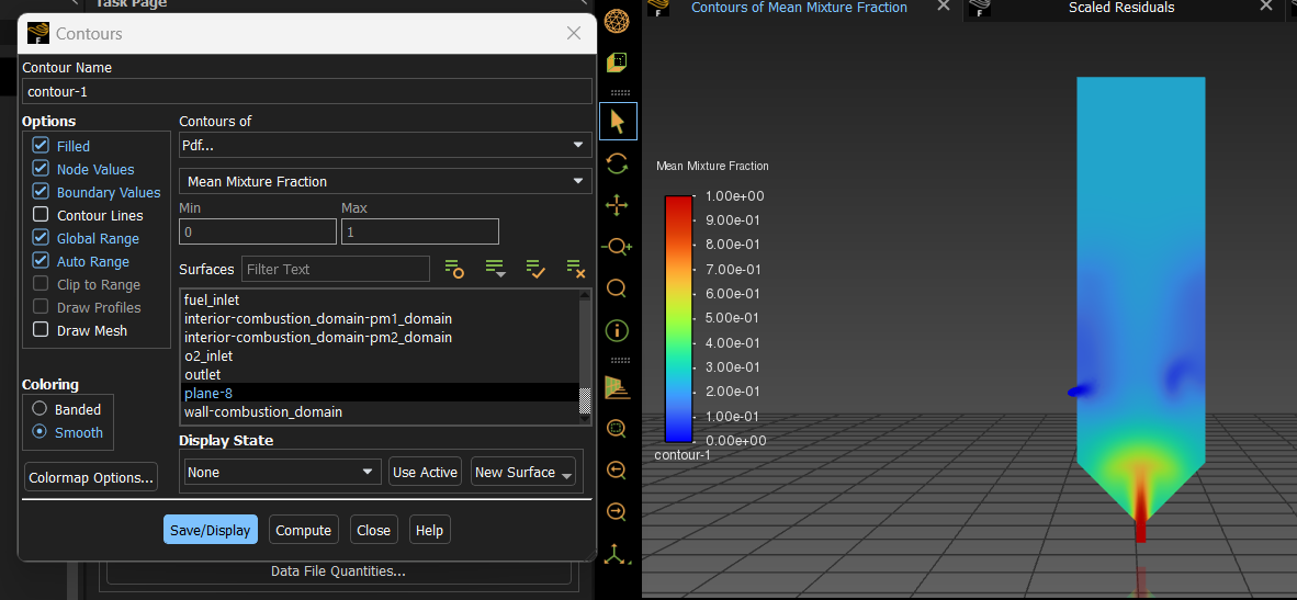
Show me a plot of mean mixture fraction?
-
April 24, 2024 at 10:48 am
Ren
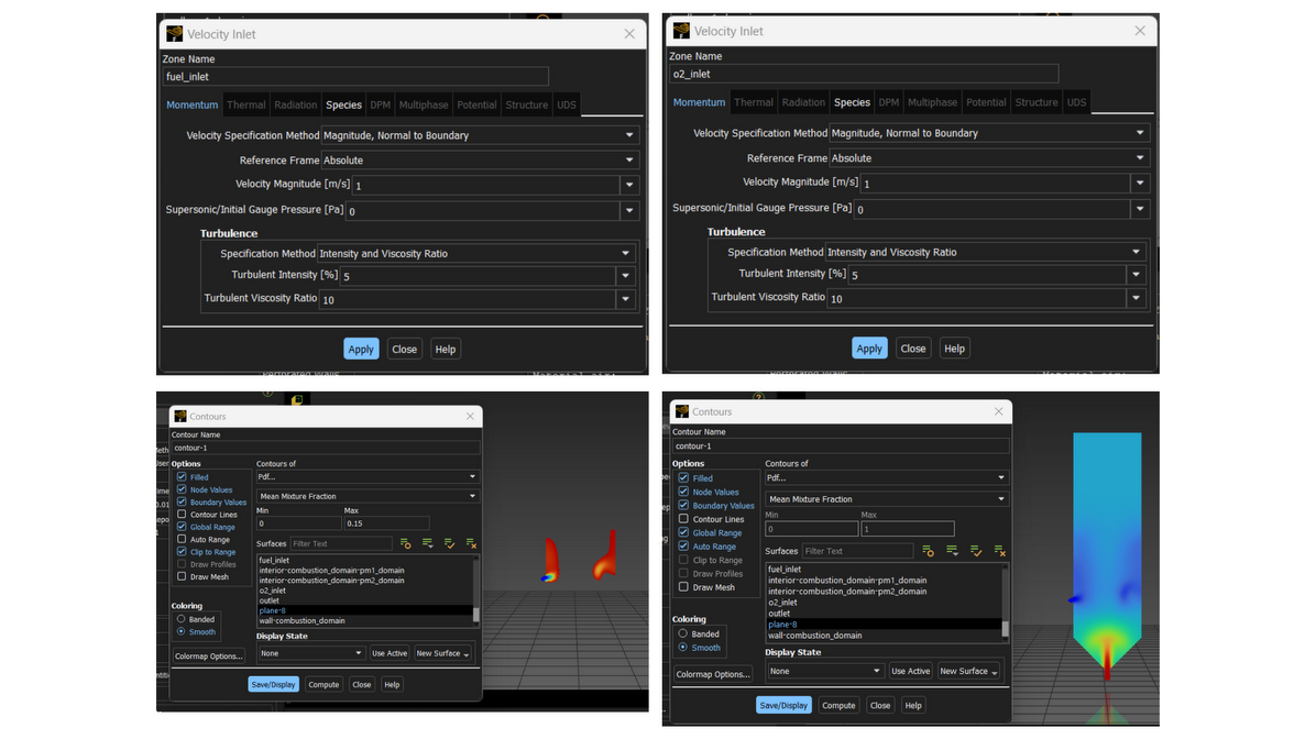
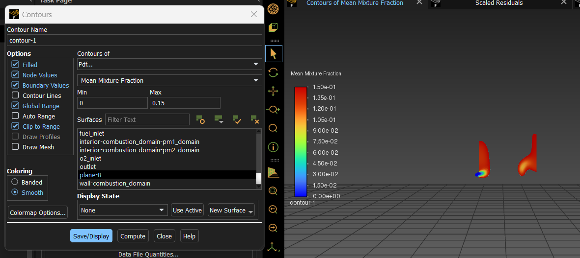
Ansys EmployeePlease set the range of the mean mixture fraction plot to [0, 0.15]
-
April 24, 2024 at 10:51 am
-
April 24, 2024 at 12:33 pm
Ren
Ansys Employeedid you see my previous questions?
-
April 24, 2024 at 4:03 pm
-
April 24, 2024 at 6:01 pm
-
April 24, 2024 at 6:13 pm
-
April 25, 2024 at 8:30 am
Ren
Ansys EmployeeYou did not show me the mass flow rates but the mean mixture fraction contour indicates that the mixture is too rich in PM2 to burn, i.e., the mixture is outside of its flammability range. Please double check your boundary conditions.
FYI, you can report the mass flow rates of all or selected boundaries using
Results->Reports->Fluxes, select "Mass Flow Rate"
-
April 25, 2024 at 9:39 am
-
April 25, 2024 at 9:49 am
Foo Sin Khai
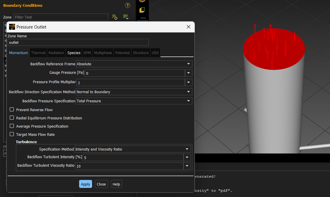
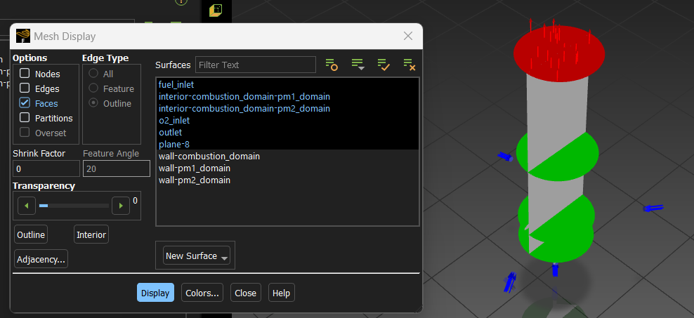
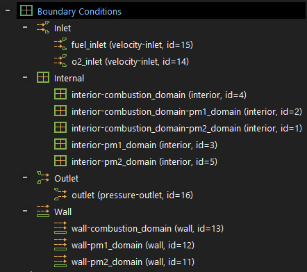
SubscriberWhen addressing the issue of a mixture being excessively rich in PM2, rendering it outside the flammability range, I need guidance on determining the appropriate boundary conditions to manage. While I can demonstrate how I've set the boundary conditions for the fuel and air inlets, I've left the rest at default settings. Could you assist me in identifying the additional boundary conditions that need adjustment?
-
April 25, 2024 at 9:56 am
Foo Sin Khai
SubscriberIn my previous message prior response outlining the boundary conditions, I specified setting the fuel inlet speed and mean mixture fraction to 1, air inlet speed to 1 and keeping the mean mixture fraction at 0. However, I couldn't modify anything for the interior. I'm not sure what adjustments are possible for the outlet and wall boundary conditions.
-
April 25, 2024 at 10:15 am
Foo Sin Khai
SubscriberI have one more question: Can Fluent actually perform transient combustion simulations in porous media? It appears that combustion behaves normally in non-porous zones, but in porous zones, it seems that combustion cannot occur transiently.
-
April 25, 2024 at 10:34 am
-
April 25, 2024 at 11:01 am
Rob
Forum ModeratorRead the manual - note the word I used was DETAILED.
The boundary conditions should replicate the real system. I'll leave Ren to comment on the combustion part, but inlet speed/massflow is something you should know as it's not something we can advise on.
-
April 25, 2024 at 12:01 pm
Foo Sin Khai
SubscriberI appreciate your guidance, Rob, throughout this process. No offense, I just wanted to ensure I'm heading in the right direction. Thank you for your support.
-
April 25, 2024 at 1:02 pm
Rob
Forum ModeratorNone taken; the uppercase was to highlight that porous media may behave differently to a real porous structure. Look up how a Davy Lamp works to see what I mean.
-
April 25, 2024 at 1:05 pm
Ren
Ansys EmployeeHi,
I noticed that you used the name o2_inlet. What actually in real world enters o2_inlet, air or pure o2?
Regarding your question on modelling transient combustion in porous media. The current model is not showing any combustion taking pace inside PM2. This is not due to the combustion model but becasue that the fuel and oxidiser have fully mixed (as evidenced by a uniform value of the mean mixture fraction) in PM2 and their proportion is outside of the flammability range. The combustion model is simply reflecting this fact.
-
April 25, 2024 at 3:06 pm
Foo Sin Khai
SubscriberI understand your point. Do you have any suggestions, such as increasing the fuel or air inlet speed, to potentially adjust the proportions and achieve the flammability range? Just to clarify, I'm referring to air, not oxygen, due to a misnaming.
-
April 25, 2024 at 3:29 pm
Ren
Ansys EmployeeIf you just wanted to have a mixture that will be combustible, then you can try to increase the air mass flow rate (not velocity) to get an air-to-fuel ratio of, say, 19. The easiest way of doing this is to change the inlet boundaries to mass-flow-inlet type so that you can enter mass flow rate (MFR) values directly. Currently, you have
fuel MFR = 1.832E-5 kg/s, so you can try
air MFR = 1.832E-5 * 19 = 3.4808E-4 kg/s
-
April 25, 2024 at 3:33 pm
Ren
Ansys EmployeeIf you prefer to use velocity, then, just increase the air velocity by a factor of 3.56
-
April 26, 2024 at 12:48 pm
-
April 26, 2024 at 1:21 pm
Rob
Forum ModeratorThat looks like a different model? What does the species field look like?
-
April 26, 2024 at 2:18 pm
-
April 26, 2024 at 2:20 pm
-
April 26, 2024 at 2:45 pm
Rob
Forum ModeratorAnd the methane fraction?
-
April 26, 2024 at 3:14 pm
Ren
Ansys EmployeeHow many reactions do you use?
Which turbulence-chemistry interaction model is used?
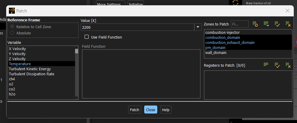
Did you numerically ignite the mixture in a region where the flame is expected by patching a high temperature value, e.g., 2200 K?
-
April 27, 2024 at 3:25 am
Foo Sin Khai
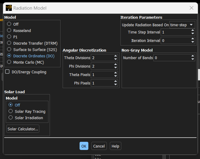
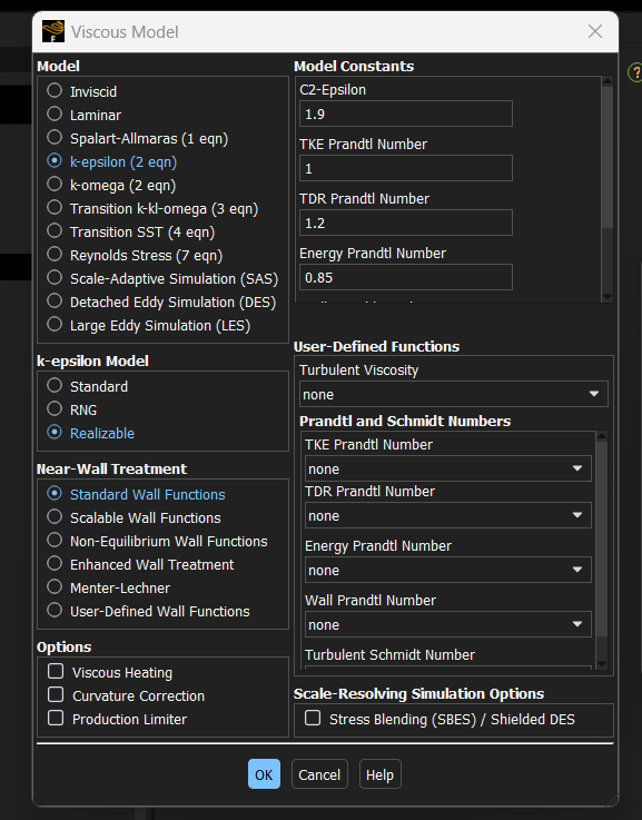
SubscriberI've already patched at 2200K, but I'm uncertain if I did it correctly. I utilized the realizable k-epsilon model and activated the discrete ordinate radiation model. However, I'm unsure about the the number of reactions you mean. This outcome was achieved using 100 time steps with a time step size of 0.01 seconds.
-
April 29, 2024 at 10:10 am
Ren
Ansys EmployeeLet's do it step-by-step:
- Show me a screenshot of the "Species Model" dialog box
- What is the diameter and length of the tube?
-
May 2, 2024 at 2:58 pm
Foo Sin Khai
SubscriberThanks a lot, Ren and Rob! Adding the spark ignition did the job. Really grateful for your help and guidance throughout.
-
May 5, 2024 at 6:10 pm
Foo Sin Khai
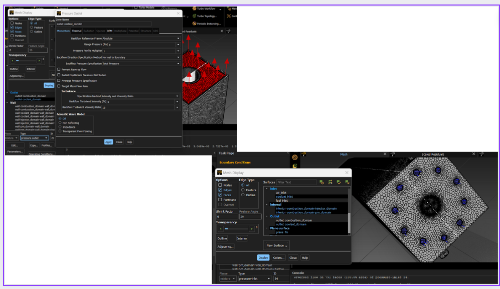
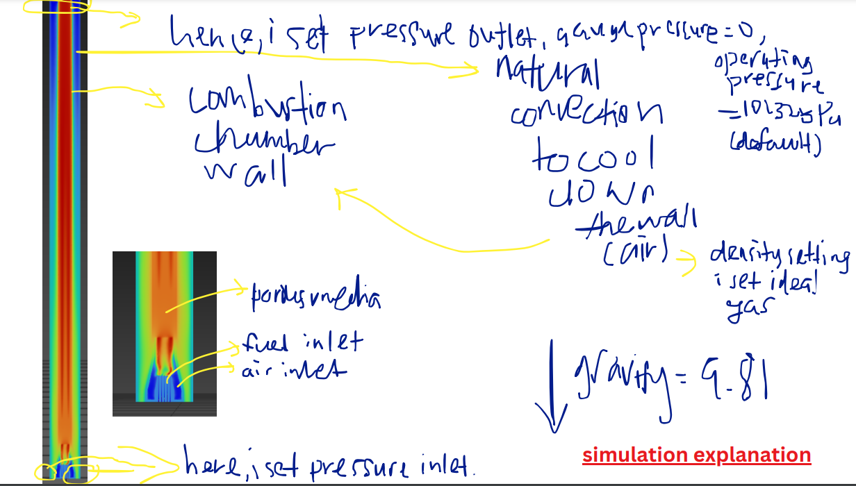
SubscriberHello, I'm encountering an issue again and really need your assistance. Currently, I'm attempting to implement natural convection to cool down the combustion chamber wall. My approach involves defining a pressure inlet and pressure outlet, but I keep encountering a problem with reversed flow. I've tried various methods to resolve this issue, such as increasing the length of the domain to ensure the outlet and inlet are not too close.
My orthogonal quality is around 0.3++, and skewness is 0.67, which seems acceptable. For the natural convection simulation, I've applied ideal gas settings for the density of air, with the operating pressure set to 101325 Pa. Gravity is enabled in the y direction with a value of -9.81, and the operating density is set to zero.
I'm not sure where the issue lies with all these settings. Additionally, when I open the pathline for the coolant inlet, nothing is shown, indicating that no flow is visible. Do you have any insights into what might be causing this? Any help would be greatly appreciated.
-
May 6, 2024 at 3:33 am
Foo Sin Khai
SubscriberThis is the pressure contour. Seem like the pressure at the inlet is very high(higher than atmospheric pressure) that block the inlet hence got reversed flow. another thing is the pressure change according to density all that?
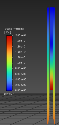
I'm aiming for the hot air to rise, decrease in density, and exit the channel, causing a pressure drop at the inlet for new air to enter. I'm not sure if my setup is correct. Could you help me check for any issues? -
May 6, 2024 at 6:48 am
Foo Sin Khai
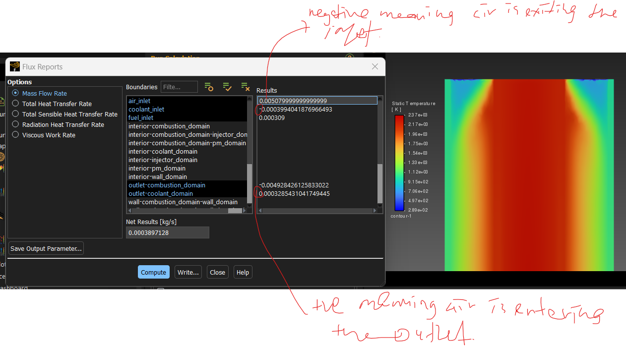
SubscriberIt seems like the reverse flow is quite significant. The negative mass flow rate at the coolant pressure inlet suggests that air is exiting at the inlet, while the positive mass flow rate at the coolant pressure outlet indicates air entering at the outlet. This indicates that hot air is stuck in the system, unable to leave, while cool air isn't entering.
I suspect there might be an issue with the design, geometry, or boundary condition setup. Do you have any suggestions on how to address this?
-
May 7, 2024 at 6:41 am
rixiu
SubscriberHi there, anybody can help? Really no idea how to solve this?????
-
May 7, 2024 at 9:19 am
Rob
Forum ModeratorHave a look at the operating density, ideally it want's to be exactly the value for the external temperature (you want to remove the density-operating_density term in the equation). I assume you're using incompressible ideal gas and have gravity on?
-
May 7, 2024 at 9:55 am
rixiu
SubscriberI'm using ideal gas, operating density i set at 0.
-
May 7, 2024 at 10:02 am
-
May 7, 2024 at 12:43 pm
Rob
Forum ModeratorInwhich case you need to account for the terms mentioned here /forum/forums/topic/natural-convection-convergence-issues/ Running models with two very different domains is not trivial.
-
May 31, 2024 at 1:46 pm
Foo Sin Khai
SubscriberHi there,
Got issue again here and really need your help... Issue: Before turn on Discrete Ordinate Radiation model, my solution can converge. (1e-6 continuity, second order-scheme.)
Setup Before Turning On Discrete Ordinate:
Steady
Realizable k-epsilon
Species Transport
For natural convection to cool down the wall this setting is set: air density properties-incompressible gas law, gravity is turn on, operating density =1.225...
Boundary condition for coolant(air) inlet: pressure-inlet
Convergence criteria: Continuity = 1e-6
Second order scheme
Result: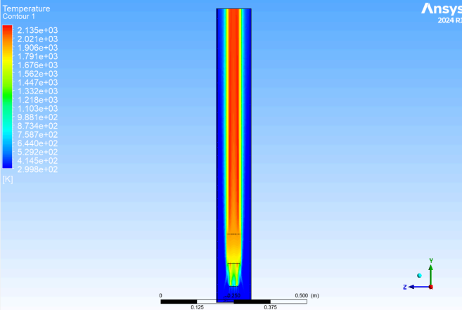
Now, i try to turn on Discrete Ordinate and run with first order scheme it cannot converge. Any idea why this happen?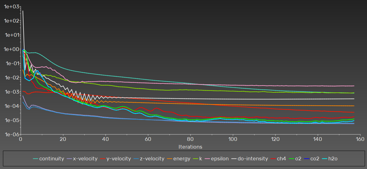
-
May 31, 2024 at 3:32 pm
Rob
Forum ModeratorNot really. Maybe try providing details and review the flow and energy results.
-
- The topic ‘Transient Porous Media Combustion’ is closed to new replies.


-
3467
-
1057
-
1051
-
929
-
896

© 2025 Copyright ANSYS, Inc. All rights reserved.

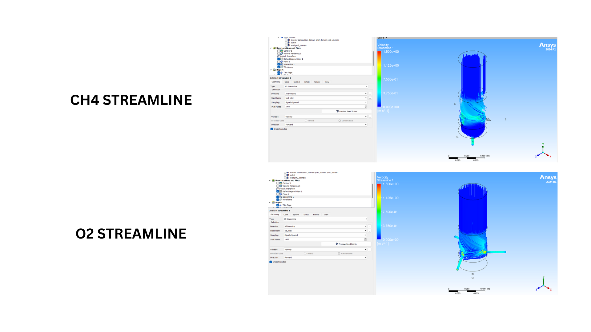
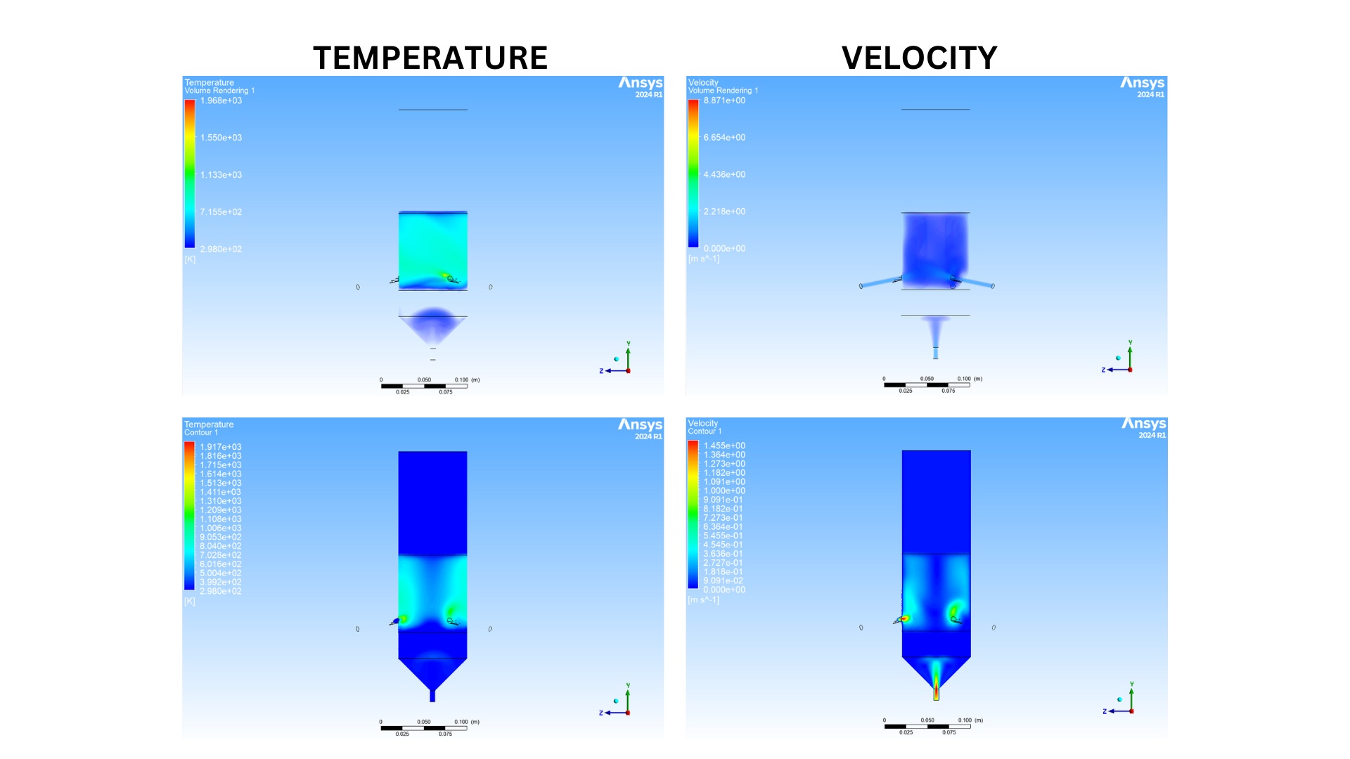

.png)
.png)
.png)
