-
-
January 10, 2019 at 7:03 pm
shantashreejena97
SubscriberHey, I am doing the analysis of a turboexpander model. but in transient structural analysis its showing error in saying that msup transient analysis cant be done using full damped or unsymmetrical solver. how could I solve this if I am doing linear analysis by mode superposition method? also, I want to know that what will be the no of substeps.
-
January 10, 2019 at 9:26 pm
Sandeep Medikonda
Ansys EmployeeHi,
Please explain with snapshots of you model and analysis settings along with the error.
Regards,
Sandeep -
January 11, 2019 at 1:08 pm
shantashreejena97
SubscriberThank you for your reply. Below is the image of my model with error and analysis settings. Can you please tell me where is the error and what should i do to do transient analysis successfully. i have given 10 mode shapes in modal analysis and my rot speed is 240000rpm. i have also taken displacement of the sleeve about Y axis as zero.
-
January 11, 2019 at 1:17 pm
jj77
SubscriberLooking at the error shown in the message section. It says that the transient analysis does not support a damped or unsymm. solve from the previous modal analysis.
Â
Â
See the rotor dynamic guide for a complete description of the capabilities, and also transient rotordynamic examples.Â
 Copy paste this into your ansys help browser (https://ansyshelp.ansys.com/account/secured?returnurl=/Views/Secured/corp/v192/ans_rot/rotbook.html).
Â
There is an apdl transient example, where the qrdamped method has been used. Try to use qrdamped in your modal analysis (in the modal analysis, and under solver type, choose reduced damped).
-
January 11, 2019 at 2:08 pm
shantashreejena97
SubscriberThank you for your reply @jj77. But I don't know how to do APDL Transient analysis. Can't this be done in the GUI method? Should I change something in my modal analysis? Is there any option that how to convert unsymmetrical solver to symmetrical.
-
January 11, 2019 at 2:11 pm
-
January 11, 2019 at 3:09 pm
-
January 11, 2019 at 3:16 pm
jj77
SubscriberIt can be tricky to do transient with using modes, that are complex
.
Â
Try not storing the complex mode shapes (see image below).
Â
Alternatively in transient one should be able to use a full method (rather than using modes, set solver type to full), using just numerical time integration of the dynamic equations. (no need to run a modal analysis prior to the transient)
-
January 11, 2019 at 4:40 pm
-
January 12, 2019 at 4:26 am
-
January 12, 2019 at 7:29 am
jj77
SubscriberJust for future reference if any one should have a a similar issue, not storing complex modes did that sort it out? Or do you run a full transient one.
As for the settings, you are simulating one second with 1/240 time step (so 240 steps) so the highest frequency you can capture has a frequency of 24 Hz there about (sampling theorem). Typically in implicit dynamics, one takes the time step as the lowest natural period (highest frequency of interest) of the system divided by ten, if we are looking at vibrations say an earthquake. If though the situation is to capture transients and impacts, then the time step needs to be several times smaller then these events. That is the theory. Now one could always use autotimesteps to let the software cut down or increase steps, but this is in other software only active for nonlinear transient dynamics. -
January 12, 2019 at 5:02 pm
shantashreejena97
SubscriberI have done mode superposition transient analysis by not storing complex modes in reduced damped solver. It has done successfully but due to the inappropriate substeps no. so many peaks are coming in the total deformation graph. Can I know is there any specific formula for knowing the no. of substeps or no of timesteps.
-
January 13, 2019 at 4:42 am
shantashreejena97
SubscriberThis is how my graph is coming(image below). I know this is a wrong graph because according to my Campbell diagram 3 critical speeds are coming in between 10 mode shapes among which 2 are in the range of 240000rpm rot vel. so according to this, I must get 3 peaks in transient analysis graph. but there are lots of peaks coming in this graph. so can anyone please tell me what analysis settings should I give so that I would get the appropriate results.
-
January 14, 2019 at 8:51 am
jj77
SubscriberSee my previous post for the time stepping settings (have in mind in the graph above you are looking at time, not frequencies, which might have some resonant peeks in them).
I would also recommend since you have an answer to your original question, mark that post with Is Solution or ask a follow-up question. Then open a New Discussion for a new question, with time step settings (include graphs of time variation of the excitation force, mode shapes, results , etc.).
-
- The topic ‘
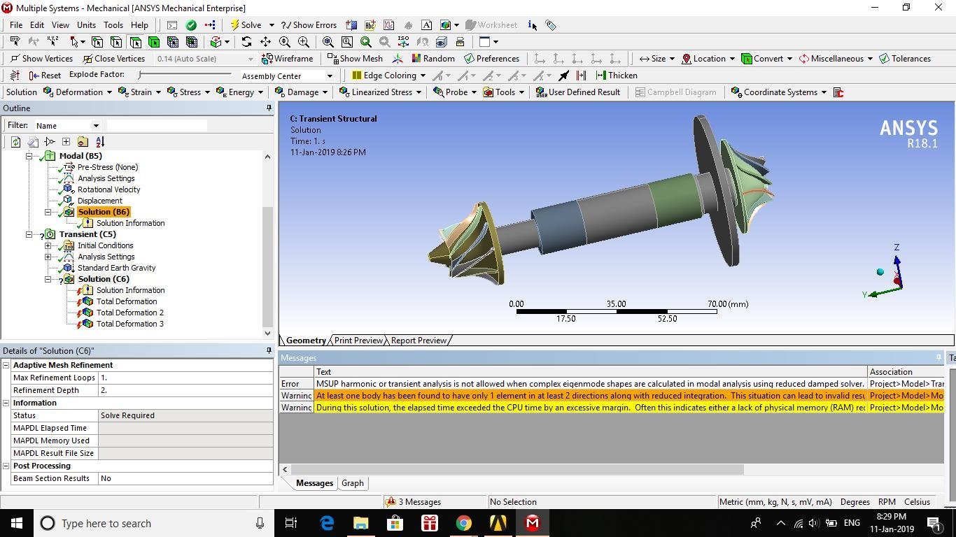
transient analysis of an turboexpander model using ansys 18.1’ is closed to new replies.
-
6029
-
1906
-
1425
-
1308
-
1021
© 2026 Copyright ANSYS, Inc. All rights reserved.


